Power factor correction sounds like something whispered in a secret electrical-engineering dungeon, right between “reactive power” and “please label that panel.” But once you break it down, the calculation is surprisingly practical. If your facility has motors, transformers, HVAC equipment, welders, compressors, pumps, or any other inductive load that likes to drink current like it found an open bar, power factor correction can help reduce wasted electrical capacity and avoid unpleasant utility charges.
In simple terms, power factor shows how efficiently electrical power is being used. A power factor of 1.0, also called unity power factor, means nearly all supplied power is being converted into useful work. A low power factor means your system is pulling extra current that does not perform useful work but still burdens cables, transformers, switchgear, and the utility grid. That extra burden often appears as reactive power, measured in kVAR.
This guide explains how to calculate power factor correction in 8 clear steps. We will cover the formulas, show examples, explain capacitor bank sizing, and point out practical details that keep the calculation from turning into a spreadsheet-shaped headache.
What Is Power Factor Correction?
Power factor correction is the process of improving a low power factor by reducing the amount of reactive power drawn from the utility. In most commercial and industrial settings, poor power factor is usually caused by inductive loads. Motors, transformers, and magnetic ballasts create a lagging power factor because current lags behind voltage.
Capacitors are commonly used to correct lagging power factor because they provide leading reactive power. Think of inductive loads as the friend who always shows up late, and capacitors as the friend who arrives early with snacks. The goal is not to create chaos; the goal is balance.
The basic power triangle includes three values:
- kW: real power, or useful working power.
- kVAR: reactive power, which supports magnetic fields but does not perform useful work.
- kVA: apparent power, the combination of real and reactive power.
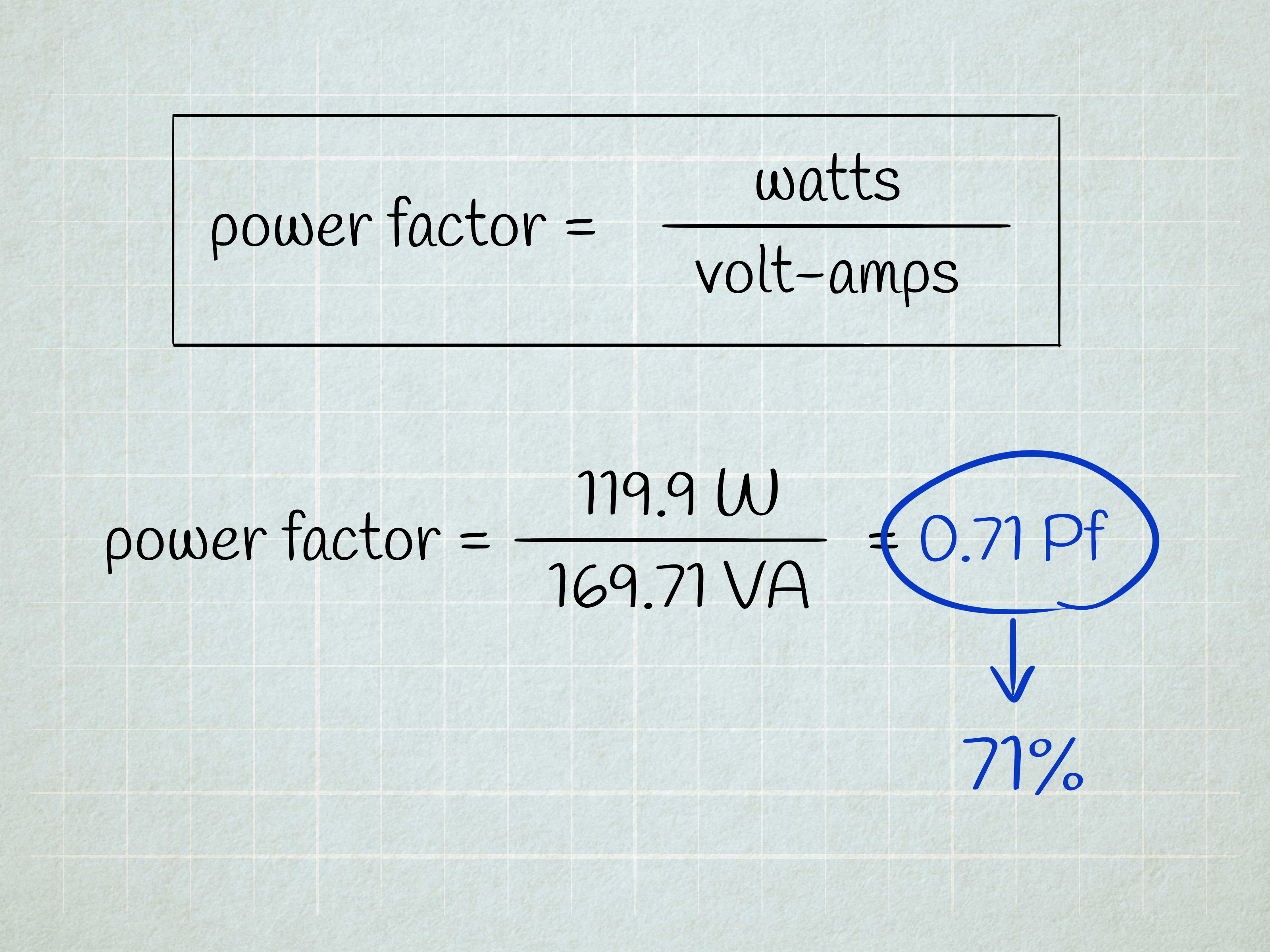
The standard power factor formula is:
For example, if a plant uses 100 kW and has an apparent power demand of 125 kVA, the power factor is:
That means only 80% of the apparent power is doing useful work. The remaining portion is not “wasted” in the same way a dripping faucet wastes water, but it still forces the electrical system to carry additional current. That extra current can increase losses, voltage drop, heat, and utility demand charges.
How to Calculate Power Factor Correction: 8 Steps
Step 1: Gather the Electrical Data
Before calculating power factor correction, collect the key operating data. You need the real power in kilowatts, the existing power factor, and the target power factor. In many facilities, this information can be found on utility bills, power quality analyzer reports, electrical meters, motor data, or energy management systems.
The most important values are:
- Existing load in kW
- Current power factor
- Desired power factor
- Operating voltage
- System type, such as single-phase or three-phase
- Load behavior, including whether the load is steady or variable
Do not guess the power factor unless this is only a classroom exercise. In real facilities, load conditions change throughout the day. A factory at full production may behave very differently from the same factory during lunch, shutdown, or maintenance. If the utility bill shows a monthly power factor, use it as a starting point, but verify with measurements when possible.
Step 2: Calculate the Existing Apparent Power
Once you know real power and existing power factor, calculate apparent power using this formula:
Suppose a facility has a 500 kW load and an existing power factor of 0.78. The apparent power is:
This tells you the utility and electrical distribution system must support about 641 kVA to deliver 500 kW of useful work. That gap matters because conductors, transformers, and switchgear are sized around current and apparent power, not just useful work. A poor power factor makes the system carry more current than necessary, like forcing a delivery truck to haul a couch, three bowling balls, and a decorative fountain just to deliver one toaster.
Step 3: Find the Existing Reactive Power
Reactive power can be calculated from the power triangle. Use this formula:
Using the same example:
This means the system is drawing about 401 kVAR of reactive power before correction. That is the electrical “foam” in the beer glass analogy: it fills the mug, but it is not the part doing productive work. Foam can be charming at a baseball game. On an electric bill, not so much.
Step 4: Choose the Target Power Factor
Common target power factor values are 0.90, 0.95, 0.97, or sometimes 0.98. Many facilities aim for 0.95 because it often provides a strong balance between utility savings, equipment cost, and reduced risk of overcorrection.
Trying to reach exactly 1.00 is usually not necessary and may create problems if the load varies. If too much capacitance is installed, the system can shift from lagging to leading power factor. That may cause voltage issues, nuisance trips, or utility concerns. In other words, unity power factor sounds heroic, but electrical systems do not need a superhero cape if a good work jacket will do.
For this example, let us target a corrected power factor of 0.95.
Step 5: Calculate the New Apparent Power
Now calculate what the apparent power would be at the target power factor:
Using our 500 kW facility:
This is a big improvement. The facility still uses 500 kW of real power, but the total apparent power required falls from about 641 kVA to about 526 kVA. That reduction can free up capacity in transformers and cables while lowering current flow.
Step 6: Calculate the New Reactive Power
Next, calculate the reactive power remaining after correction:
For the example:
After correction to 0.95 power factor, the system would need only about 164 kVAR from the utility instead of about 401 kVAR. The difference is the amount of reactive power that must be supplied locally by capacitors or another correction system.
Step 7: Calculate the Required Capacitor kVAR
The required capacitor size is the difference between the existing reactive power and the target reactive power:
In our example:
So, the facility needs approximately 237 kVAR of power factor correction. In real equipment selection, you would usually round to a standard capacitor bank size, such as 225 kVAR, 240 kVAR, or 250 kVAR, depending on available products, load profile, and engineering review.
There is another common formula used by engineers and capacitor manufacturers:
In that formula, φ1 is the angle of the existing power factor, and φ2 is the angle of the target power factor. This method is widely used in power factor correction charts and calculator tables. The math looks fancy, but the mission is the same: find how much reactive power must be supplied locally to move from the current power factor to the desired one.
Step 8: Select the Correct Correction Method
After calculating the required kVAR, choose the correction method. The main options include fixed capacitors, automatic capacitor banks, detuned capacitor banks, active harmonic filters, and variable frequency drives with built-in power factor improvement.
A fixed capacitor can work well for a single motor or a steady load. However, if the facility load changes throughout the day, an automatic capacitor bank is usually better. It switches capacitor stages on and off as demand changes. This prevents overcorrection during light-load periods and provides more accurate compensation during production peaks.
For systems with many variable frequency drives, nonlinear loads, LED drivers, UPS systems, or harmonic distortion, do not simply throw capacitors at the problem and hope the electrons behave. Capacitors can interact with system harmonics and create resonance. In those cases, detuned capacitor banks or harmonic filtering may be needed.
Also remember that capacitor installations involve stored energy, switching equipment, fusing, ventilation, discharge resistors, conductor sizing, and code compliance. Power factor correction should be designed or reviewed by a qualified electrical professional. The calculation is friendly; the panel is not a toy.
Power Factor Correction Example
Let us summarize the example in a simple table.
| Item | Value |
|---|---|
| Real power | 500 kW |
| Existing power factor | 0.78 |
| Target power factor | 0.95 |
| Existing apparent power | 641.03 kVA |
| Existing reactive power | 401.15 kVAR |
| New apparent power at 0.95 PF | 526.32 kVA |
| New reactive power | 164.34 kVAR |
| Required correction | 236.81 kVAR |
The practical selection might be a 240 kVAR automatic capacitor bank, assuming the system study confirms that this size is appropriate. If the load changes often, the bank might be divided into steps such as 30, 60, 60, and 90 kVAR. That way, the controller can add or remove correction gradually instead of slamming the system with one giant electrical “ta-da.”
Why Power Factor Correction Matters
It Can Reduce Utility Penalties
Many utilities charge commercial and industrial customers when power factor falls below a required level. The threshold varies by utility and tariff, but values such as 0.85, 0.90, or 0.95 are common in many rate structures. Poor power factor forces the utility to provide extra current capacity, and utilities are not famous for giving away capacity as a complimentary appetizer.
It Can Free Electrical Capacity
Improving power factor reduces current for the same real power load. Lower current can free capacity in transformers, switchgear, feeders, and generators. This is especially valuable when a facility wants to add equipment but is close to the limit of existing electrical infrastructure.
It Can Improve Voltage Conditions
High current causes voltage drop across conductors. By reducing unnecessary reactive current, power factor correction can improve voltage at equipment terminals. Better voltage can help motors run cooler and more reliably, especially in long feeder applications.
It Can Lower System Losses
Electrical losses in conductors are related to current. When current drops, resistive losses also drop. In many facilities, the savings from loss reduction alone may not justify a power factor correction project, but it is a welcome bonus. Think of it as finding a few extra fries at the bottom of the bag.
Common Mistakes When Calculating Power Factor Correction
Using Nameplate Data Instead of Real Measurements
Nameplate values are useful, but they do not always represent actual operating conditions. A motor may run lightly loaded, heavily loaded, intermittently, or with variable speed control. A calculation based only on nameplate data can oversize or undersize the correction equipment.
Correcting to 1.00 Without a Good Reason
Correcting all the way to unity power factor can be risky in variable-load systems. If production drops but the capacitors remain connected, the system may become leading. Most facilities are better served by a realistic target such as 0.95 or 0.97.
Ignoring Harmonics
Capacitors and harmonics can be a dramatic couple. If a facility has nonlinear loads, the correction system should be evaluated for harmonic resonance. Detuned capacitor banks or active filters may be necessary.
Installing Capacitors Only at the Service Entrance
Service entrance correction may satisfy the utility meter, but it may not reduce current throughout the facility. Correcting closer to large inductive loads can reduce current in more of the internal distribution system. The best location depends on the load profile, layout, and maintenance strategy.
Power Factor Correction Formula Cheat Sheet
Use these formulas when calculating power factor correction:
For three-phase systems, if you need to estimate apparent power from voltage and current, use:
For single-phase systems, use:
These formulas are useful for preliminary calculations, but final equipment selection should account for load variation, harmonic distortion, switching method, ambient temperature, enclosure rating, utility requirements, and applicable electrical codes.
Field Experience: What Calculating Power Factor Correction Teaches You
In real-world power factor correction projects, the first lesson is that the math is only the beginning. The formula may say “install 240 kVAR,” but the building may respond with, “Cute idea, but have you met my load schedule?” A manufacturing plant rarely behaves like a textbook. Compressors cycle. Pumps start and stop. HVAC loads rise in the afternoon. Welders create sudden demand spikes. A facility that looks stable on paper may behave like a caffeinated squirrel when production is running.
One practical experience is that measurement duration matters. A quick meter reading can give a snapshot, but a power quality logger over several days gives a story. That story shows when the power factor drops, how long it stays low, and whether the problem is tied to one process, one shift, or one large motor. Without that context, it is easy to install correction that works beautifully for one hour and awkwardly for the other twenty-three.
Another field lesson is that automatic capacitor banks are often worth the extra planning. Fixed capacitors can be simple and cost-effective, but they are not flexible. If the load varies, an automatic bank can switch stages to match real demand. This is especially helpful in facilities with seasonal production, multiple shifts, or equipment that does not operate continuously. The controller quietly does the work while everyone else argues about who left coffee in the break room microwave.
Location also matters more than beginners expect. Installing capacitors at the main service may reduce utility penalties, but it may not reduce current inside branch circuits feeding the actual inductive loads. Correcting near large motors can reduce current through upstream feeders, improve voltage conditions, and reduce heating. However, distributed correction can be harder to maintain and may require careful coordination with motor starters and overload protection.
Harmonics deserve respect. Facilities with variable frequency drives, rectifiers, UPS systems, or other nonlinear loads should not select plain capacitors without checking distortion levels. Capacitor banks can shift resonance points and may amplify harmonic currents. In these environments, detuned banks or harmonic filters are often the safer choice. This is where a power quality study stops being “extra paperwork” and becomes the thing that prevents expensive electrical drama.
The best experience-based advice is simple: calculate, measure, verify, then select. Do not buy a capacitor bank because the number looks close. Confirm the utility billing structure, target power factor, load behavior, available fault current, ventilation, enclosure requirements, and maintenance access. A good power factor correction project should lower electrical stress and improve billing performance without creating new problems. Done correctly, it is one of those rare upgrades that makes the electrical system happier and the accounting department slightly less terrifying.
Conclusion
Learning how to calculate power factor correction is mostly about understanding the relationship between kW, kVA, and kVAR. Start with the real load, determine the existing power factor, choose a sensible target, calculate existing and target reactive power, and then size the capacitor bank based on the difference.
The basic calculation is straightforward, but real-world application requires judgment. Load variation, harmonics, correction location, utility rules, and safety requirements all affect the final design. A well-sized correction system can reduce utility penalties, improve available capacity, lower current, support better voltage, and help equipment operate more efficiently. A poorly selected system can create overcorrection, resonance, or maintenance headaches. Electrons may be invisible, but they are very good at leaving clues when ignored.