A three-way smart switch gives an ordinary lighting circuit a useful digital upgrade. You can still turn the lights on at the bottom of the stairs and off at the top, but you also gain app control, schedules, voice commands, scenes, and the ability to check whether someone left the hallway glowing like an airport runway.
The project is more complicated than replacing a basic single-pole switch. A traditional three-way circuit contains two traveler wires, two switching locations, and a common connection that serves a different purpose in each electrical box. Smart switches add another layer because they may require a neutral wire, a matching companion device, a specific line-side location, or a manufacturer-approved wiring arrangement.
This guide explains how to install a three-way smart switch safely in an existing U.S. residential circuit. Because switch models and household wiring differ, always treat the instructions supplied with your exact product as the final authority. If the wiring does not match the manufacturer’s diagram, stop and call a licensed electrician rather than improvising a creative new relationship between copper and electricity.
Research basis: Electrical work should be de-energized, tested, completed within the user’s skill level, and performed according to applicable codes and product instructions.
What Is a Three-Way Smart Switch?
A three-way circuit controls one light or group of lights from two locations. Common examples include switches at both ends of a hallway, near two entrances to a room, or at the top and bottom of a staircase. Despite the name, a standard three-way switch does not have three operating locations. A circuit controlled from three or more locations normally includes one or more four-way switches between the two three-way switches.
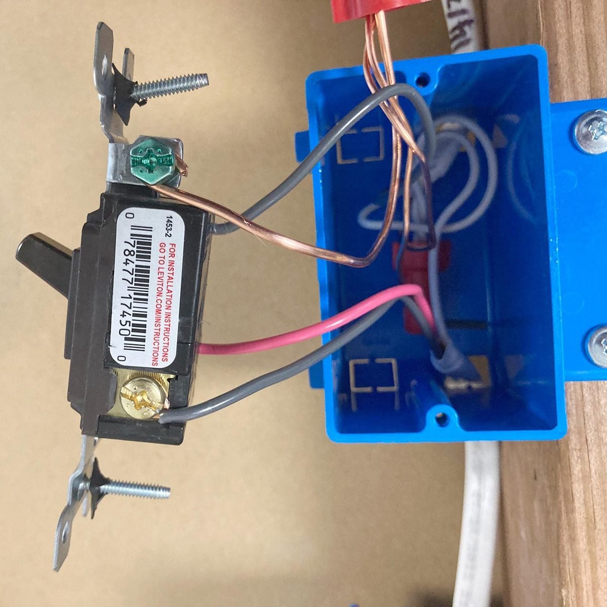
A traditional three-way switch usually has four connections:
- One common terminal: Usually marked by a dark or black screw.
- Two traveler terminals: Usually marked by two matching brass-colored screws.
- One ground terminal: Normally a green screw connected to a bare copper or green grounding conductor.
At one end of the circuit, the common terminal is typically connected to incoming line power. At the other end, the common terminal usually connects to the switched wire feeding the light. The travelers run between the two switch locations and allow either switch to change the light’s state.
Wire colors can be helpful clues, but they are not proof of a wire’s function. Older wiring, previous renovations, switch loops, and creative past homeowners can turn the usual color conventions into little more than optimistic suggestions. Label conductors according to their original terminals and the manufacturer’s wiring diagram, not color alone.
Research basis: Three-way switches use a common connection, two travelers, and a ground, while the line and load are normally located at opposite ends of the switching circuit.
Choose the Correct Three-Way Smart Switch
Do not buy a single-pole smart switch and assume that positive thinking will make it work in a three-way circuit. The product must specifically support three-way or multi-location control.
Check the Required Three-Way Configuration
Manufacturers use several different designs:
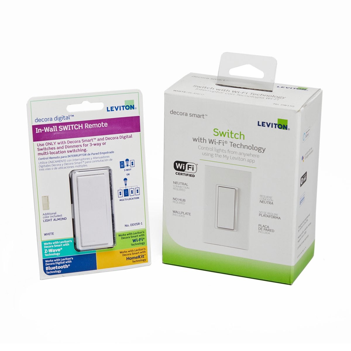
- One smart switch plus one standard three-way switch: Some products replace only one existing switch and continue working with the mechanical switch at the other location.
- A smart master plus a wired companion: Other systems require the second switch to be replaced with a matching accessory or companion device.
- A two-device smart kit: Some dimmer kits contain dedicated main and satellite units that must be installed together.
- A smart switch plus a wireless wall remote: Certain systems replace one wired switch and use a battery-powered or wireless companion at the second location.
These designs are not interchangeable. For example, some smart switches are explicitly incompatible with a conventional three-way switch, while others are designed to use one. Follow the approved configuration for the exact model number printed on the switch and packaging.
Determine Whether a Neutral Is Required
Most Wi-Fi smart switches need continuous power for their radios and internal electronics, even while the light is off. Many obtain that power through a neutral connection. In a switch box, neutrals are commonly grouped together under a wire connector and may not be attached to the old mechanical switch.
However, not every older switch box contains a neutral. Some no-neutral smart switches are available, but they may have restrictions involving bulb type, minimum electrical load, companion devices, or required adapters. Never connect a smart switch’s neutral lead to the ground wire. Neutral and equipment ground serve different purposes and are not substitutes.
Check the Electrical Load
Confirm that the switch is rated for the connected lighting load. A switch designed for LED lamps may have different limits for incandescent, fluorescent, fan, or motor loads. If you are installing a smart dimmer, verify that the bulbs are dimmable and that the dimmer supports their type and combined wattage.
Check the Network Requirements
Many Wi-Fi switches use a 2.4 GHz network during setup, while hub-based and newer products may use other wireless protocols. Review app, hub, Wi-Fi, Bluetooth, and smartphone requirements before opening the electrical box. Discovering that you need a hub after the switch is mounted is not dangerous, but it is an excellent way to make a 45-minute project last all afternoon.
Research basis: Manufacturer-approved three-way arrangements vary significantly. Some products use a standard switch, while others require a companion, paired kit, or wireless remote; neutral requirements also vary by model.
Tools and Materials You May Need
- Three-way-compatible smart switch, kit, or companion device
- Manufacturer’s installation guide or in-app wiring instructions
- Noncontact voltage tester
- Approved contact-type voltage tester or multimeter, if you are trained to use one
- Phillips and flat-head screwdrivers
- Wire stripper and cutter
- Needle-nose pliers
- Electrical tape and wire labels
- Phone or camera for wiring photographs
- Listed wire connectors rated for the conductor material, size, and quantity
- Compatible wall plate
- Flashlight or headlamp
A headlamp is surprisingly valuable because the first official step in electrical work is turning off the one circuit that would have provided convenient lighting.
How to Install a Three-Way Smart Switch
Step 1: Read the Product Instructions Completely
Locate the model number and open the correct installation diagram before touching the existing switches. Determine whether you are replacing one switch, both switches, or one switch plus a companion. Also identify which electrical box must contain the main smart device.
Some models must be installed on the line side, where constant incoming power is available. Others can be installed in either location, provided the conductors are rearranged exactly as shown in the instructions. Do not assume every brand uses terminals with the same names or functions.
Step 2: Shut Off Power at the Breaker
Turn on the existing light, locate the correct breaker, and switch it off. Confirm that the light goes out, but do not treat that as sufficient proof that the box is safe. Multi-gang boxes can contain conductors from more than one circuit, and labeling inside electrical panels is not always accurate.
Test your voltage tester on a known energized source so you know it works. Then test the switches and conductors before touching them. After testing the circuit, verify the tester again on a known live source. If any conductor remains energized, stop and identify every circuit supplying the box.
Research basis: Safety organizations and manufacturers consistently instruct installers to shut off the breaker and test for voltage before handling conductors.
Step 3: Remove Both Wall Plates and Inspect the Boxes
Remove the wall plates and switch mounting screws. Pull each switch forward carefully without disconnecting anything. Avoid placing stress on old or brittle insulation.
Inspect both boxes for:
- Loose, scorched, cracked, or damaged wires
- Aluminum branch-circuit wiring
- Missing grounding connections
- Overcrowded or unusually shallow boxes
- Multiple circuits entering the same box
- A neutral bundle, usually containing white conductors
- Splices that do not resemble the product’s approved diagrams
Stop and contact an electrician if you find burned insulation, melted connectors, aluminum wiring you are not qualified to handle, unexplained voltage, or a wiring arrangement you cannot confidently document.
Step 4: Photograph and Label Every Connection
Take wide photographs showing the entire box and close-ups showing the screw colors and wire positions. Photograph both switch locations before loosening a terminal.
Label the wire connected to the old switch’s dark common screw as COMMON. Label the two conductors connected to the matching traveler screws as TRAVELER 1 and TRAVELER 2. Mark the ground conductor and neutral bundle as well.
Do not label the common wire as line or load unless its function has been positively determined. The common is usually line in one box and load in the other. Confusing those two locations is one of the most common reasons a smart switch loses power when the second switch is operated.
Research basis: Manufacturer instructions recommend photographing the original wiring, identifying travelers by their matching terminals, and distinguishing the line/load common connections.
Step 5: Confirm Which Box Receives the Main Smart Switch
Compare the labeled conductors and neutral availability with the product diagram. If the model requires the main switch on the line side, you must positively identify the box containing constant incoming power. Do not energize exposed wiring or perform live diagnostic testing unless you are qualified and equipped to do so safely.
If the line and load locations cannot be identified from the existing connections, cable routing, and approved instructions, this is the correct moment to call an electrician. Guessing produces symptoms ranging from a switch that repeatedly goes offline to a breaker that trips immediately. The second symptom is the house issuing a formal complaint.
Step 6: Disconnect the Old Switches
With power verified off, disconnect one conductor at a time. Keep every label attached. If the old switch uses push-in back-wire connections, use the release slot or cut and re-strip the conductor when appropriate. Do not reuse damaged, heavily nicked, or badly oxidized wire ends.
Strip conductors only to the length specified by the smart-switch and wire-connector manufacturers. Too little exposed copper can create a weak connection; too much can leave energized metal outside the terminal or connector.
Step 7: Connect the Ground and Neutral
Connect the smart switch’s grounding terminal or green lead to the equipment-grounding conductors according to the instructions. Keep the existing grounding continuity intact, including any required bond to a metal box.
If the switch requires a neutral, connect its neutral lead to the existing neutral bundle using an approved connector. Do not remove other neutrals from the circuit, attach the neutral to a random white conductor, or use the bare ground as a substitute.
Some older circuits use a white conductor as an ungrounded or switched conductor. Such a wire should be re-identified as required, but its white insulation does not magically turn it into a neutral. When the wiring function is uncertain, stop.
Step 8: Connect Line, Load, Common, and Travelers
Follow the exact diagram for your model. A typical smart switch may include terminals or leads labeled LINE, LOAD, TRAVELER, NEUTRAL, and GROUND. A companion switch may use only a traveler, neutral, and ground, while a two-device kit may require both existing travelers to connect in a particular order.
General three-way concepts are useful for understanding the circuit, but they are not a substitute for the product diagram. A traveler terminal on one brand can perform differently from a traveler or communication terminal on another.
Tighten screw terminals to the manufacturer’s specified torque when a value is provided. Tug each conductor gently to confirm it is secure. Check that no bare copper is exposed outside terminals or wire connectors, except for the grounding conductors where permitted.
Research basis: Smart-switch terminal arrangements are model-specific; manufacturers provide approved line, load, traveler, neutral, ground, and companion wiring diagrams that must be followed.
Step 9: Arrange the Wires and Mount the Devices
Smart switches are deeper than many mechanical switches. Fold the conductors into the box carefully rather than forcing the device backward with the mounting screws. Keep wire connectors behind the switch and avoid pinching insulation against sharp box edges.
If the device cannot fit without extreme pressure, the box may be too shallow or overfilled. Do not solve this problem by crushing the conductors into submission. A qualified electrician can install a larger code-compliant box or determine whether another switch design is more suitable.
Align the switches, tighten the mounting screws evenly, and install the wall plate. Leave removable air-gap tabs, service switches, or reset controls accessible as required by the manufacturer.
Step 10: Restore Power and Test Manual Operation
Stand clear of the switches and restore the breaker. If the breaker trips, you hear buzzing, or you notice smoke, sparks, a burning odor, or rapid heating, turn the breaker off immediately. Do not repeatedly reset a tripping breaker.
Before configuring the app, test the physical controls:
- Turn the light on and off from the first location.
- Operate the second switch and repeat the test.
- Try both switches in several alternating sequences.
- For a dimmer, confirm smooth dimming without flicker or unexpected shutoff.
The lighting should respond correctly regardless of the previous position of either control. If one switch works only while the other is in a particular position, a common or traveler connection is probably incorrect.
Step 11: Complete App and Network Setup
Download the official manufacturer app and follow its pairing procedure. You may need to enable Bluetooth, connect your phone to a supported Wi-Fi band, scan a setup code, or add a compatible smart-home hub.
Give the switch a specific name such as “Upstairs Hall Lights” instead of “Switch 1.” Clear names make voice commands and automation routines much easier to manage. After setup, install available firmware updates, configure schedules, and confirm that remote control works when your phone is not connected to the home Wi-Fi network.
Common Three-Way Smart Switch Problems
The Smart Switch Has No Power
The switch may be installed in the wrong box, the line conductor may be on the wrong terminal, a required neutral may be missing, or a wire connector may be loose. Turn off the breaker before inspecting any connections.
The Light Works From Only One Location
This usually indicates that the common and a traveler were swapped, the travelers were connected incorrectly, or the second device is incompatible with the main smart switch.
The Switch Goes Offline When the Other Switch Is Used
A smart switch that requires constant power may have been installed on the load side or wired so the mechanical switch interrupts its power. Check the manufacturer’s approved three-way configuration.
The LED Bulbs Flicker or Glow When Off
Possible causes include incompatible bulbs, a non-dimmable LED connected to a dimmer, a load below the product’s minimum, loose wiring, or a no-neutral switch that requires a bypass or bulb adapter. Use only manufacturer-approved solutions.
The Breaker Trips
Turn the breaker off and leave it off. A tripping breaker can indicate a short circuit, pinched conductor, incorrect terminal connection, damaged insulation, or grounding fault. Do not continue experimenting until the wiring has been inspected.
The Switch Feels Hot
Slight warmth can be normal for some electronic controls, especially dimmers. Excessive heat, discoloration, odor, buzzing, or a wall plate that becomes uncomfortably hot requires immediate shutdown and professional inspection.
Research basis: Common three-way failures include misplaced line/load conductors, incorrect traveler or common connections, incompatible companion devices, and model-specific neutral or load issues.
When You Should Hire an Electrician
Call a licensed electrician when:
- No neutral is present and your selected switch requires one.
- The existing circuit does not match an approved manufacturer diagram.
- You find aluminum wiring, damaged insulation, scorch marks, or overheated connectors.
- The box contains more than one circuit and you cannot safely isolate all power.
- You cannot confidently distinguish the common, travelers, line, and load.
- The electrical box is too small for the new device and conductors.
- The circuit lacks proper grounding.
- The breaker trips after installation.
- The switch buzzes, smells hot, sparks, or becomes excessively warm.
- Local rules require a permit, inspection, or licensed electrical work.
Hiring an electrician is not an admission of DIY defeat. It is often the fastest way to prevent an inexpensive switch from becoming an expensive wall-repair, troubleshooting, or fire-damage project.
Practical Experiences and Lessons From Three-Way Smart Switch Installations
The most useful lesson from real-world smart-switch projects is that the physical installation often takes less time than understanding the existing wiring. A homeowner may remove the wall plate expecting four neatly organized conductors and instead discover six wire connectors, three cables, two circuits, and one mysterious white wire wrapped in electrical tape from an era when dinosaurs apparently performed residential renovations.
Photographs Are More Valuable Than Memory
Many installation problems begin with the sentence, “I was sure I would remember where that wire went.” Once several conductors have been disconnected, the original arrangement can become surprisingly difficult to reconstruct. Photographing both switches from several angles and labeling the common before removing it creates a reliable path back to the original setup.
A particularly helpful habit is to include the screw colors in the photograph. The old switch’s dark common screw communicates more useful information than the insulation color of the attached conductor. A black wire can be a traveler, a line, or a switched load depending on the circuit.
The Neutral Bundle Is Easy to Miss
DIYers sometimes conclude that a box has no neutral because no white wire is connected to the existing switch. Mechanical switches normally do not need a neutral, so the neutral conductors may be folded into the back of the box under a wire connector. Carefully inspecting the box before buying a product can prevent a frustrating return trip.
The opposite mistake is assuming every white wire is neutral. In older switch-loop arrangements, a white conductor may carry power and should have been marked accordingly. Treating that conductor as neutral can cause immediate malfunction or create a dangerous fault.
Compatibility Matters More Than Brand Recognition
Another common surprise is learning that “three-way compatible” does not describe one universal wiring method. One smart switch may work with the existing mechanical switch. Another may require a proprietary companion. A third may include a main and satellite device that cannot be replaced individually.
The most reliable buying strategy is to download the installation guide before ordering. Compare its diagrams with the conductors and neutral bundles visible in both wall boxes. This ten-minute check is much easier than discovering halfway through installation that the main device must go in the box with line power and neutral, while your preferred location has neither.
Box Space Can Become the Real Project
Traditional switches are relatively shallow. Smart switches contain radios, control electronics, heat-management components, and larger terminal assemblies. Even when the wiring is correct, fitting the device into an older metal or shallow plastic box can feel like trying to pack a winter coat into a sandwich bag.
Organized wire folding makes a major difference. Place connectors toward the back corners, fold conductors in gentle accordion shapes, and avoid stacking every splice directly behind the deepest part of the switch. Never use the mounting screws as a mechanical press. If the device will not seat normally, stop and address the box capacity.
Test the Hardware Before Blaming the App
Smart-home apps are frequent suspects when a newly installed switch behaves strangely, but incorrect three-way wiring often appears to be a software problem. A switch that goes offline whenever the companion is toggled may be losing its constant power. A light that operates from only one location usually points to a traveler or common error rather than weak Wi-Fi.
Complete the manual switching test first. Only after both wall controls work in every sequence should you pair the device, install firmware, create schedules, or connect voice assistants. Separating electrical testing from network setup turns one confusing problem into two manageable checkpoints.
The final lesson is simple: stopping is a legitimate DIY skill. When the wiring does not match the diagram, repeated trial-and-error connections are not troubleshooting; they are gambling with a circuit breaker as the referee. Good installers know how to make secure connections, but they also know when the safest tool in the bag is a licensed electrician’s phone number.
Conclusion
Installing a three-way smart switch can add convenient app control, automation, scheduling, and voice operation without sacrificing control from two physical locations. Success depends on choosing a product that matches the circuit, documenting the original wiring, identifying the common and traveler conductors correctly, and following the exact model-specific diagram.
Turn off the breaker, test every conductor before touching it, and never substitute ground for neutral. After wiring, confirm normal operation from both locations before beginning app setup. When the circuit is damaged, unusually configured, missing required conductors, or simply unclear, bring in a licensed electrician. Smart lighting should make life more convenientnot make the breaker panel the most exciting part of your weekend.