Sheet metal bending looks simple from across the shop: a flat piece of metal goes into a machine, pressure is applied, and out comes a crisp angle that somehow fits perfectly into an enclosure, bracket, duct, cabinet, panel, chassis, or mystery part that only the engineer and one very patient fabricator understand. Easy, right? Not quite. Bending sheet metal is where geometry shakes hands with metallurgy, where a few thousandths of an inch can make or break a project, and where the humble bend line deserves more respect than it gets at family dinners.
At its best, sheet metal bending is both practical craft and applied science. The craft is in knowing how metal behaves in the real world: how aluminum may crack if pushed too hard, how stainless steel can act like it pays rent in the press brake, and how a tiny burr can become a tiny villain. The science is in bend allowance, bend deduction, K-factor, inside bend radius, springback, tooling, grain direction, and tolerance planning. Together, these ideas help designers and fabricators turn a flat blank into a strong, accurate, manufacturable part.
This guide explains the core principles behind bending sheet metal, the most common methods, the design choices that prevent expensive mistakes, and the shop-floor experience that separates a clean bend from a metal pancake with ambition.
What Is Sheet Metal Bending?
Sheet metal bending is a forming process that changes the shape of a flat sheet by applying force along a straight or curved line. The material is not cut apart; it is plastically deformed. In plain English, the metal is persuadedfirmlyto take a new shape and stay there. This process is used across automotive manufacturing, aerospace components, electronics enclosures, HVAC ductwork, appliance panels, medical devices, architectural features, farm equipment, and custom fabrication.
The most familiar bending tool is the press brake, a machine that uses a punch and die to form bends at controlled angles. Other bending equipment includes folding machines, panel benders, roll benders, hand brakes, and specialized forming tools. Each method has its place. A thin decorative panel might be perfect for a folder, while a heavy industrial bracket may need the tonnage and control of a hydraulic or electric press brake.
The Physics Behind a Bend
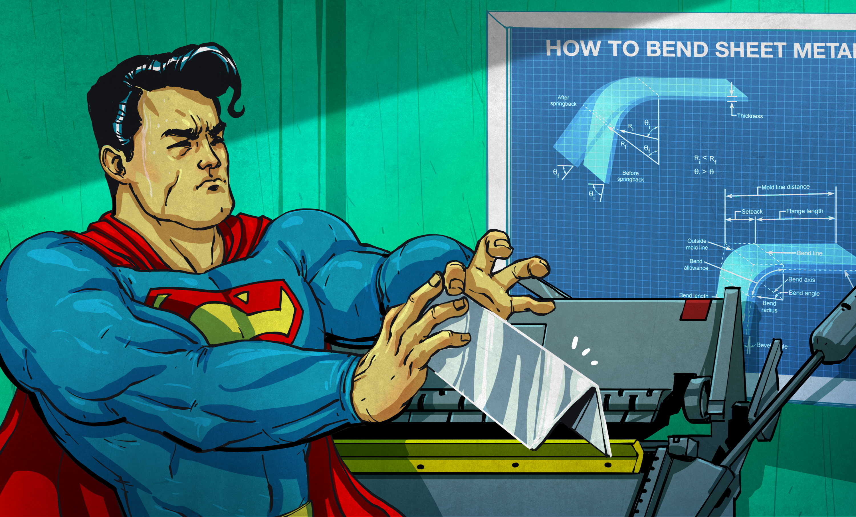
When sheet metal bends, the outside of the bend stretches while the inside compresses. Between those two zones is the neutral axis, an imaginary layer in the material that does not significantly stretch or compress. The location of that neutral axis matters because it affects the final flat pattern size. Designers who ignore it may discover that their finished part is too short, too long, or just “artistically inaccurate.”
This is where the K-factor enters the conversation. K-factor describes the position of the neutral axis relative to material thickness. It is not a magic number pulled from a machinist’s lunchbox; it changes based on material type, thickness, bend radius, tooling, and bending method. A correct K-factor helps software and fabricators calculate how much material is consumed in the bend.
Bend Allowance and Bend Deduction
Bend allowance is the arc length of the bend measured along the neutral axis. It is used when calculating the length of the flat blank before bending. Bend deduction is the amount subtracted from the combined outside dimensions of the flanges to determine the flat pattern. Both concepts are different paths toward the same goal: making sure a part comes out the right size after forming.
Think of it like baking, except the cookie sheet is steel and the oven can exert several tons of force. If the flat pattern is wrong, the finished bend will not land where it should. In one-off projects, that may mean a little rework. In production, it can mean an entire batch of parts that fit about as well as a screen door on a submarine.
Common Sheet Metal Bending Methods
Air Bending
Air bending is one of the most common press brake methods. The punch pushes the material into a V-die, but the sheet does not bottom out completely against the die. The final angle depends on punch depth, material behavior, tooling, and springback. Air bending is flexible because one tool setup can produce multiple angles, but it requires careful control and accurate compensation.
Bottoming
In bottoming, the punch presses the sheet more fully into the die. This method can improve angle consistency, but it requires more force than air bending and is less flexible. It is often used when tighter angle control is needed and the tooling is appropriate for the material and thickness.
Coining
Coining uses very high pressure to force the material into the die shape. It reduces springback but demands much greater tonnage and can mark or thin the material. Coining is less common in many modern shops because air bending with CNC controls and good tooling is often more efficient.
Roll Bending
Roll bending forms curves rather than sharp angles. It is used for cylinders, cones, curved panels, tanks, architectural metalwork, and decorative pieces. Instead of one crisp bend line, the sheet passes through rollers that gradually form the curve. It is the metalworking equivalent of convincing a flat sheet to develop a graceful personality.
Why Bend Radius Matters
The inside bend radius is the radius on the inside surface of the bend. It is one of the most important design choices in sheet metal fabrication. A radius that is too tight can cause cracking, distortion, excessive stress, or unpredictable springback. A larger radius usually reduces stress but changes part geometry and flat pattern calculations.
A common design guideline is to use an inside bend radius close to the material thickness for many general sheet metal parts, but that rule is only a starting point. Softer materials may accept tighter bends, while harder or heat-treated materials often require larger radii. For example, mild steel is generally more forgiving than 6061-T6 aluminum, which is known for being strong but not always cheerful about tight bending.
Keeping bend radii consistent across a part also helps reduce cost. When every bend uses a different radius, tooling changes increase setup time. Designers who standardize radii make life easier for fabricators, and fabricators tend to remember such kindness.
Material Choice: Not All Metals Bend the Same
Sheet metal bending depends heavily on material properties. Mild steel is widely used because it is strong, affordable, weldable, and generally cooperative. Stainless steel offers corrosion resistance but often requires more forming force and may show more springback. Aluminum is lightweight and corrosion resistant, but some alloys crack more easily than others. Copper and brass can bend beautifully, though they may require special attention to surface finish and softness.
Material temper matters too. Annealed material bends more easily than hardened material. A designer who specifies the right alloy but ignores temper may still run into forming trouble. This is especially important in aerospace, electronics, and structural applications where material performance and dimensional accuracy are both critical.
Grain Direction: The Hidden Line in the Metal
Most sheet metal is rolled during production, and that rolling process creates a grain direction. Bending parallel to the grain can increase the risk of cracking, especially in less ductile materials. Bending perpendicular or transverse to the grain is often preferred when the part design allows it. Grain direction is one of those details that seems minor until a bend opens up like it has trust issues.
For parts with several bends in different directions, designers and fabricators must balance blank layout, material usage, strength, appearance, and crack prevention. Sometimes the best solution is to adjust the bend radius, change the material temper, revise the blank orientation, or add relief cuts to reduce stress.
Springback: Metal’s Little Act of Rebellion
Springback is the tendency of metal to partially return toward its original shape after bending pressure is released. It happens because the material has elastic recovery. The harder and stronger the material, the more springback may appear. Stainless steel and certain aluminum alloys can show noticeable springback, while softer materials may behave more predictably.
Fabricators compensate for springback by overbending slightly, selecting the right tooling, adjusting machine settings, and using proven bend data. Modern CNC press brakes can store bend programs and corrections, but experience still matters. A machine can follow instructions with impressive precision; it cannot always sense when a material batch is being dramatic.
Design for Manufacturability: Bends That Shops Appreciate
Good sheet metal design begins long before the part reaches the press brake. A beautiful 3D model can still be difficult, expensive, or impossible to bend if it ignores fabrication rules. Design for manufacturability, often called DFM, helps avoid that problem.
Keep Holes Away From Bend Lines
Holes, slots, louvers, embosses, and cutouts placed too close to a bend can distort during forming. The material stretches and compresses near the bend, so nearby features may become oval, warped, or misaligned. A practical design leaves enough distance between features and bend lines to protect accuracy.
Use Bend Relief When Needed
Bend relief cuts reduce tearing and distortion where a bend meets an edge or another formed feature. Reliefs are especially useful on tabs, boxes, trays, and parts with adjacent flanges. They may look like small notches, but they do big work by giving the metal somewhere to move.
Avoid Tiny Flanges
Very short flanges can be difficult to form because the material may not sit properly in the die. Minimum flange length depends on material thickness, tooling, and die opening. If a flange is too small, the press brake setup becomes less stable and accuracy suffers. In design terms, a tiny flange may be cute; in fabrication terms, it may be a tiny headache wearing a hard hat.
Plan Tolerances Realistically
Bent sheet metal parts have tolerances influenced by cutting, material thickness variation, tooling, bend angle, springback, and the number of bends. Tighter tolerances are possible, but they usually require more process control, inspection, setup time, or secondary operations. Smart tolerance planning identifies which dimensions truly matter and which ones can be allowed to breathe.
Tooling: The Shape Behind the Shape
Press brake tooling includes punches and dies that determine how force is applied to the sheet. Tool selection affects bend radius, angle accuracy, surface marks, minimum flange length, and required force. A sharp punch may create a tight bend but can increase cracking risk or leave marks. A wider die opening may reduce tonnage but create a larger natural inside radius.
Tooling also affects appearance. Cosmetic parts may need protective film, urethane tooling, polished tools, or special handling to avoid scratches. A bracket hidden inside a machine may not care about tool marks. A visible stainless steel appliance panel definitely cares and may complain through the customer service department.
Press Brake Safety: Respect the Machine
Sheet metal bending equipment can be extremely powerful. Press brakes create pinch-point hazards, and operators must use proper safeguarding, training, lockout procedures, and personal protective equipment. Common safeguards may include presence-sensing devices, two-hand controls, pullback or restraint systems, guards, safe work procedures, and regular inspection.
Safety is not a decorative poster on the wall. It is part of the bending process. Sharp sheet edges can cut, large panels can swing during forming, and foot-pedal controls can introduce accidental cycling risks. Well-run shops treat safety as a production tool because injured people and damaged parts are both bad for business, morale, and the general vibe of a Tuesday morning.
Quality Control: Measuring the Bend
Quality control in sheet metal bending includes checking bend angles, flange lengths, hole positions, flatness, surface finish, and overall fit. Shops may use angle gauges, calipers, height gauges, coordinate measuring machines, templates, first-article inspection, and in-process checks. The more bends a part has, the more small variations can stack up.
Good quality control is proactive. It starts with material verification, tooling selection, program review, and first-piece approval. Waiting until the end of a production run to discover that every part is slightly wrong is like checking the map after driving into a lake.
Digital Tools and Modern Fabrication
Modern sheet metal bending often begins in CAD software. Designers create 3D models, assign material thickness, set bend radii, define K-factors, and generate flat patterns. CAM software and CNC press brakes then translate that information into cutting and bending operations. Digital manufacturing platforms can also provide design feedback before production, helping teams catch problems early.
However, software is only as good as the data behind it. Default K-factors, generic bend tables, and idealized material assumptions may not match a specific shop’s machines, tooling, and materials. The best results come when digital design and shop-floor knowledge work together. CAD may draw the dream, but the press brake reveals the truth.
Common Sheet Metal Bending Mistakes
Several mistakes appear again and again in sheet metal projects. One is choosing a bend radius that is too tight for the material. Another is placing holes too close to bends. A third is ignoring grain direction. Designers may also forget to account for finish thickness, hardware installation, weld distortion, or assembly clearance. Even bend sequence can become a problem if one flange blocks access to another bend.
Another common mistake is treating all metals as interchangeable. A part designed for mild steel may not bend the same way in stainless steel. A design that works in 5052 aluminum may fail in 6061-T6. When material changes, bend data should be reviewed instead of copied with reckless optimism.
Specific Example: Designing a Simple Bent Bracket
Imagine a U-shaped bracket for holding a small electronic module. The designer starts with 16-gauge steel, two 90-degree bends, mounting holes, and a powder-coated finish. A good design would specify a practical inside bend radius, keep the mounting holes away from the bend zones, allow clearance for powder coating, and avoid flanges so short that the tooling cannot form them reliably.
If the same bracket is changed to aluminum to save weight, the designer should review alloy selection and bend radius. If the bracket becomes stainless steel for corrosion resistance, springback and forming force may change. If the bracket must look polished and visible, tooling marks and grain direction become more important. One simple bracket can quickly become a masterclass in humility.
The Art Side of Bending Sheet Metal
The art of bending sheet metal lives in judgment. Experienced fabricators can often predict trouble before it happens. They notice whether a bend is too close to a cutout, whether a flange will collide during the bend sequence, whether a material is likely to spring back more than expected, and whether the drawing dimensions make sense for inspection.
This intuition is not guesswork. It is experience built from thousands of bends, good notes, occasional mistakes, and the ancient shop tradition of learning from the one part that came out wrong and taught everyone a lesson. The art is knowing when to adjust, when to ask the designer for a revision, when to change tooling, and when to stop and investigate before turning expensive material into modern sculpture.
The Science Side of Bending Sheet Metal
The science is equally important. Bend allowance, bend deduction, tensile strength, elongation, yield strength, grain direction, tool radius, die opening, and springback all shape the final part. These variables can be measured, modeled, tested, and improved. Scientific thinking allows shops to create repeatable processes instead of relying on luck and heroic amounts of coffee.
In high-quality fabrication, the art and science are not enemies. They are partners. The numbers guide the setup; the operator verifies reality. The CAD model defines the intent; the formed part proves whether the process worked. The best bending operations combine accurate data, skilled people, well-maintained equipment, and designs that respect the limits of the material.
Field Experiences: What Bending Sheet Metal Teaches You Over Time
People who spend time around sheet metal bending often learn that the material has a memory, a mood, and occasionally a sense of humor. One of the first lessons is that metal rarely forgives assumptions. A drawing may say 90 degrees, but the material may spring back to 92 unless the process compensates. The flat pattern may look perfect on screen, but a wrong K-factor can make the final flange land just far enough off to ruin an assembly. The experience is humbling in the best possible way.
Another lesson is that communication saves parts. Designers who talk with fabricators early tend to get better results. A five-minute discussion about bend radius, grain direction, hole placement, or finish requirements can prevent hours of rework. Many experienced shops can suggest small design changes that reduce cost without hurting performance. A bend moved slightly away from a hole, a radius standardized across the part, or a relief cut added to a corner can turn a difficult job into a smooth one.
There is also a strong lesson in sequencing. A part may have several bends that are individually simple but collectively tricky. Bend them in the wrong order and the part may collide with the tooling or block access to the next bend. This is where experienced press brake operators shine. They do not just form metal; they plan a choreography. Each bend has to happen at the right time, in the right orientation, with the right support. It is less like brute force and more like metal origami with consequences.
Handling sheet metal also teaches respect for edges and surfaces. Freshly cut sheet can be sharp. Cosmetic surfaces can scratch if handled carelessly. Large panels can flex, swing, or become awkward to control. In professional environments, safe handling, proper support, deburring, protective film, and teamwork matter as much as machine settings. The part is not finished simply because it has the right angle; it must also be safe, clean, consistent, and ready for assembly or finishing.
One of the most valuable experiences is seeing how small details scale in production. On a single prototype, a slight angle correction or hand adjustment may be manageable. On a run of hundreds or thousands of parts, that same issue becomes expensive. Repeatability is the real goal. Good shops record tooling, material, bend programs, inspection results, and corrections so the next run does not restart from zero. The best fabricators build a library of knowledge one job at a time.
Finally, sheet metal bending teaches patience. Rushing setup can create scrap. Ignoring material variation can create surprises. Skipping inspection can create assemblies that fight back later. The experienced approach is steady: understand the design, verify the material, choose the tooling, form a first piece, inspect it, adjust as needed, and then produce with confidence. It may not sound glamorous, but when a flat sheet becomes a precise, strong, beautiful part, there is a quiet satisfaction in it. The bend is not just an angle; it is proof that planning, physics, and skilled hands can agree on something useful.
Conclusion
The art and science of bending sheet metal come together in every bracket, enclosure, panel, duct, tray, and formed component. The process may look straightforward, but successful bending depends on understanding material behavior, bend radius, K-factor, bend allowance, springback, tooling, grain direction, safety, and manufacturability. A good bend is not an accident. It is the result of smart design, accurate calculations, practical experience, and respect for the material.
For designers, the lesson is clear: build parts that can actually be formed. For fabricators, the mission is equally clear: turn design intent into repeatable reality. When both sides work together, sheet metal bending becomes more than a manufacturing step. It becomes a disciplined craft where flat metal gains structure, strength, and purposewithout turning into scrap with a dramatic backstory.
Note: This article is written for publication and synthesizes real manufacturing, engineering, and safety principles from reputable U.S.-focused fabrication resources without inserting source links or citation artifacts into the body copy.