Note: This article is written for historical, educational, and editorial purposes. Spark gap transmitters produce wideband radio emissions, involve high voltage, and are not appropriate for on-air use. Think museum bench, spectrum analyzer, and safety barriernot weekend pirate-radio adventure.
Introduction: When Old Radio Technology Gets a Modern Plot Twist
A modern spark gap transmitter using a rotary gap sounds like something invented by a mad scientist who owns both an oscilloscope and a top hat. In reality, it is a fascinating collision between early radio history and present-day electronics curiosity. The basic idea is simple enough: a spark excites a tuned circuit, the circuit rings like an electrical bell, and the result is a burst of radio-frequency energy. The rotary gap adds timing, rhythm, and a certain mechanical drama that a plain fixed spark gap simply cannot provide.
Before vacuum tubes, transistors, software-defined radios, and tiny wireless chips began doing the heavy lifting, spark transmitters were the kings of wireless communication. They helped prove that radio waves could travel through space, carried Morse code across water, and made early wireless operators feel like they were commanding lightning in a box. They also sprayed energy across the spectrum with the manners of a leaf blower in a library.
That is why the modern version is best understood as a technical demonstration, not a communication tool. It shows how early radio worked, why engineers moved away from spark, and why today’s radio rules take unwanted emissions very seriously. The rotary spark gap makes the subject even more interesting because it introduces controlled repetition: instead of letting sparks happen whenever voltage and air breakdown feel like negotiating, the rotating electrodes determine when the discharge occurs.
What Is a Spark Gap Transmitter?
A spark gap transmitter is one of the earliest forms of radio transmitter. It uses a high-voltage spark as a fast switch to dump stored electrical energy into a resonant circuit. That resonant circuit, commonly described as an LC tank circuit, contains capacitance and inductance. When excited, it oscillates at a radio frequency and radiates energy through an antenna or coupled circuit.
The important detail is that the spark itself is not a clean radio oscillator. It is more like a hammer striking a bell. The bell rings at its natural frequency, but the sound fades quickly. In radio terms, that fading burst is called a damped wave. Instead of producing a steady continuous wave like a modern transmitter, a spark transmitter produces a sequence of short, decaying RF bursts.
Early operators used those bursts for Morse code. Press the key and the transmitter spits out a buzzing train of sparks; release it and the buzz stops. To the receiver operator wearing headphones, dots and dashes became audible bursts. Romantic? Absolutely. Efficient and neighbor-friendly? Not even close.
Why the Rotary Gap Matters
A fixed spark gap is simply two electrodes separated by air. Once voltage rises high enough to ionize the air, the gap conducts, the tank circuit discharges, and the cycle begins again. This works, but the timing can be irregular. Electrode condition, humidity, voltage rise, spacing, and circuit behavior all affect when the spark fires. The result may sound raspy, rough, and electrically untidy.
A rotary spark gap changes the personality of the transmitter. Instead of relying only on a fixed air gap, a spinning wheel carries electrodes past stationary electrodes. When the moving and fixed points align, the gap distance becomes short enough for a spark to occur. The rotation therefore controls the break rate, or the number of discharges per second.
That timing is the secret sauce. A rotary gap can make the received tone more regular, more musical, and easier to distinguish from random static. In historic systems, synchronous rotary gaps were timed with the AC generator so that sparks occurred at favorable points in the voltage waveform. This helped improve consistency and efficiency compared with rougher spark arrangements.
Synchronous vs. Asynchronous Rotary Gaps
A synchronous rotary spark gap is tied to the power source frequency or generator timing. Its electrodes meet at predictable points in the electrical cycle, so the spark tends to fire at consistent voltage peaks. This can produce a cleaner tone in the receiver, at least by spark-era standards. Calling it “clean” by modern RF standards would be like calling a steam locomotive “low profile,” but for its time, it was a major improvement.
An asynchronous rotary gap is not locked to the AC waveform. It still provides mechanical interruption, but the firing moments may wander relative to the voltage cycle. That can produce irregular spark energy and a rougher received sound. In a demonstration setting, this difference is one of the most interesting things to observe: same basic concept, very different personality.
A Modern Demonstration With Classic Bones
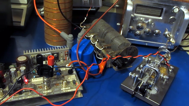
Modern hobby demonstrations of spark transmitters often combine contemporary control electronics with very old RF principles. A signal generator or solid-state switching stage may drive an ignition coil, while the high-voltage output feeds a spark gap and resonant tank. In some demonstrations, a rotary gap adds repeatable timing and creates a distinctive tone that can be heard on a nearby receiver.
This blend is educational because it separates the jobs inside the system. The modern electronics can control timing or drive power. The ignition coil steps voltage upward. The spark gap acts like a violent little switch. The tank circuit rings. The receiver hears the repetition rate as audio. Suddenly, radio history becomes visible, audible, and slightly theatrical.
But the same demonstration also explains why spark transmitters disappeared. Their emissions are broad. Their pulses are messy. Harmonics and spurious energy can show up where they are not invited. Modern radio services depend on controlled bandwidth, predictable modulation, and transmitters that stay in their lane. A spark transmitter is historically charming precisely because it does not behave like that.
The Sound of Spark: Why It Buzzes, Whines, or Sings
One of the most memorable features of a spark gap transmitter is the sound it makes in a receiver. The RF bursts may be far above human hearing, but the repetition rate of the sparks is in the audio range. If the gap fires a few hundred times per second, the receiver output becomes a tone. If the firing is irregular, the sound becomes a buzz, hiss, or angry insect auditioning for a horror movie.
Rotary gaps can make this sound more orderly. A well-timed rotary gap may produce a steady note because each spark arrives at a more regular interval. Historic accounts of synchronous rotary spark transmitters often describe them as musical or distinctive. That does not mean they were pure continuous-wave transmitters. They were still spark systems producing damped waves. However, compared with a crude fixed gap, they could sound refinedrefined in the way a chainsaw quartet is refined if all four chainsaws are in tune.
The RF Problem: Damped Waves and Wide Bandwidth
The main technical weakness of spark transmission is damping. Each spark creates an oscillation that quickly decays. A short burst in time corresponds to broad energy in frequency. In simple terms, the quicker and messier the burst, the wider its spectral footprint tends to be.
Modern transmitters are designed to concentrate energy where it belongs. A legal amateur radio transmitter, broadcast transmitter, or commercial wireless device must limit unwanted emissions. Spark systems do the opposite by nature. Even when connected to a tuned circuit, the energy is not a narrow, stable carrier in the modern sense. It is a repeating series of RF thumps.
This is why modern spark gap transmitter demonstrations should be treated as shielded, low-power, educational experiments rather than radio operations. A spectrum analyzer can reveal the lesson better than any romantic description: the signal does not politely occupy one neat channel. It spreads, rings, and throws spectral confetti.
Legal Reality: Why Spark Belongs Off the Air
In the United States, radio emissions are regulated by the FCC, and damped-wave emissions are forbidden under federal rules. Amateur radio rules also require operators to use no more bandwidth than necessary and to reduce spurious emissions as much as practicable. A spark transmitter is fundamentally at odds with those principles.
That legal context matters because many people discover spark transmitters through maker videos, vintage radio pages, or Tesla coil projects and assume “old” means “harmless.” It does not. A small spark transmitter may still interfere with nearby receivers. A stronger one can create problems over a much wider area. The fact that it looks like antique science does not give it a magical exemption from modern spectrum management.
The safe framing is simple: study it, simulate it, measure it in controlled conditions, or view it in a museum-style demonstration. Do not put it on an antenna and start calling CQ like it is 1910 and the spectrum is still mostly empty.
Historical Roots: From Marconi to Fessenden
The spark gap transmitter was central to the early wireless era. Guglielmo Marconi’s early radio systems used spark technology for wireless telegraphy. These systems proved that messages could travel without wires, especially over water, where ships and shore stations found enormous value in radiotelegraphy.
Reginald Fessenden pushed the technology in another direction. He believed continuous waves were the future, especially for speech and more efficient communication. While true continuous-wave systems required alternators, arcs, and later vacuum tubes, Fessenden’s synchronous rotary spark work represented an important transitional step. His rotary gap systems produced more consistent, readable tones than rough spark systems, even though they were still not true continuous-wave transmitters.
By the 1920s, vacuum tube transmitters were taking over. Tubes could generate continuous waves, support voice transmission, reduce interference, and use spectrum more efficiently. Spark technology became obsolete not because it lacked drama, but because better engineering arrived and quietly asked the lightning machine to leave the building.
Why Modern Builders Still Care
So why would anyone revisit a spark gap transmitter today? The answer is education. A rotary spark gap demonstration shows several ideas at once: resonance, high-voltage switching, damping, RF radiation, modulation by interruption, electromagnetic interference, and the history of regulation. That is a lot of teaching packed into one noisy device.
It also bridges communities. Vintage radio enthusiasts see the ancestry of wireless telegraphy. High-voltage hobbyists recognize similarities with Tesla coil switching. RF engineers see a walking cautionary tale about bandwidth. Makers see a mechanical-electrical hybrid with sparks, timing, and sound. Everyone gets somethingexcept the neighbors, who should ideally get silence.
Modern Spark Gap Transmitter SEO Keywords in Context
For readers searching the topic, the most useful related phrases include modern spark gap transmitter, rotary spark gap, spark gap radio, damped wave transmitter, RF interference, LC tank circuit, and early wireless telegraphy. These terms belong together because the subject is not merely a gadget; it is a lesson in how radio evolved from brute-force sparks to precise electromagnetic communication.
Safety Considerations Without the Boring Lecture Voice
High voltage deserves respect. A spark gap transmitter can involve charged capacitors, ignition coils, exposed conductors, ozone, ultraviolet light, hot electrodes, and unexpected RF energy. Even a modest system can surprise someone who assumes “low power” means “low danger.” Capacitors can store energy after power is removed. Sparks can ignite vapors. RF noise can annoy equipment. And yes, the sound may convince family members that a small portal has opened in the garage.
Responsible demonstrations use shielding, distance, interlocks, proper discharge procedures, dummy loads or heavily attenuated coupling, and measurement equipment instead of real antennas. The point is to understand the physics without becoming the reason nearby radios start making haunted kazoo noises.
What the Rotary Gap Teaches Better Than a Diagram
A diagram can show a spark gap as a switch. A rotary spark gap shows that switch becoming a timing instrument. As electrodes approach, the electric field intensifies. At breakdown, the gap conducts. As the rotor moves on, the arc is interrupted and the circuit can recharge. That sequence turns raw voltage into rhythmic pulses.
This is why rotary gaps are so visually compelling. They make the invisible timing of early radio physical. You can imagine the rotor as a conductor in an orchestra where the musicians are capacitors, inductors, plasma, and poor life choices. When the timing improves, the tone improves. When the timing wanders, the receiver tells on you immediately.
Experience Notes: What Working Around Rotary Spark-Gap Demonstrations Teaches You
Spending time around rotary spark-gap demonstrations changes the way you think about radio. Modern wireless devices hide their complexity. A phone connects to a tower, Wi-Fi fills a room, Bluetooth pairs with earbuds, and everything feels smooth enough to be mistaken for magic. A spark gap transmitter is the opposite. It refuses to hide. It flashes, snaps, smells faintly metallic, and announces every discharge like a tiny thunderstorm with scheduling issues.
The first lesson is that timing matters. When a rotary gap is adjusted in a demonstration, the receiver does not respond politely; it reacts immediately. A more regular break rate can turn a ragged buzz into a clearer tone. A poor setup sounds unstable, as if the signal is dragging one foot behind it. This gives a practical feel for why early operators cared about spark rate, coupling, and tuning. They were not polishing details for fun. They were trying to be heard through static, weather, primitive receivers, and other stations that were also flinging sparks into the ether.
The second lesson is that resonance is not an abstract classroom word. In a spark system, the tank circuit is the voice. Change the resonant behavior and the whole character of the signal changes. The spark may be the dramatic part, but the tuned circuit determines the ringing. That is a valuable reminder for anyone learning RF: the loudest component is not always the smartest component.
The third lesson is humility. A spark gap transmitter makes interference easy to understand because it is so good at creating it. After seeing a broadband display on test equipment, modern emission rules stop looking like bureaucratic paperwork and start looking like traffic lanes on a busy highway. Without those lanes, every transmitter becomes the person merging across four lanes while eating soup.
The fourth lesson is respect for historical engineers. It is tempting to laugh at spark technology because it is obsolete, noisy, and inefficient. But early wireless pioneers were solving problems with the materials and theory available to them. They built systems before modern oscillators, precision components, and semiconductor devices existed. A rotary spark gap was not crude in its original context; it was clever mechanical timing applied to an electrical frontier.
The fifth lesson is that demonstrations need boundaries. The most successful modern spark-gap experiences are controlled, brief, measured, and honest about their risks. They do not pretend spark is a practical transmitter today. Instead, they use it as a living fossil: a way to hear what early radio sounded like, see why continuous waves won, and appreciate how far spectrum discipline has come.
In that sense, a modern spark gap transmitter using a rotary gap is not really about reviving dead technology. It is about understanding why the technology died, why it mattered while it lived, and why its ghost still makes engineers smile. Preferably from behind a safety shield.
Conclusion: The Beautifully Noisy Ancestor of Modern Radio
A modern spark gap transmitter with a rotary gap is part history lesson, part RF warning label, and part mechanical theater. The rotary gap adds timing and tone to a technology that once powered the wireless telegraphy age. It helps explain why early operators could hear distinctive signals, why Fessenden’s work mattered, and why spark systems were eventually replaced by continuous-wave transmitters and vacuum tube technology.
At the same time, it reminds us that radio spectrum is shared space. What was acceptable in the early wireless era is not acceptable in today’s crowded RF environment. Spark transmitters are fascinating, but their broad emissions and legal problems make them unsuitable for real communication. Their best modern role is educational: a controlled demonstration that lets us see, hear, and measure the rough beginnings of radio.
The rotary spark gap is the star because it turns chaos into rhythm. It does not make spark radio modern in the legal or technical sense, but it makes the old machine easier to understand. And understanding is the real payoff. The spark may be obsolete, but the lesson still crackles.