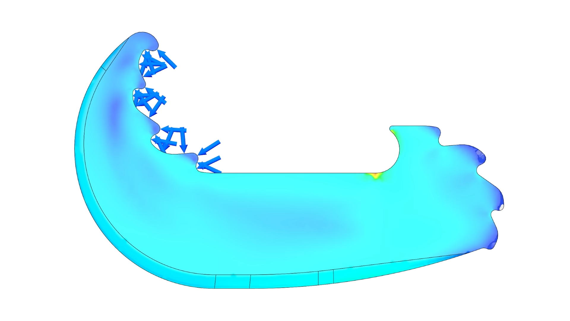
Fifty grams of plastic does not sound like heavy-lifting equipment. It sounds like a slightly overenthusiastic keychain. Yet a carefully engineered, single-piece PLA hook reportedly survived a load of 1,122 kilogramsroughly 2,474 poundsduring a 3D-printing design challenge.
The result was not achieved by discovering enchanted filament, bribing gravity, or quietly hiding a steel cable inside the print. The competition prohibited internal reinforcement and limited each entry to 50 grams of material. The winning design succeeded because its creator treated geometry, load paths, print orientation, contact surfaces, and testing as parts of one engineering system.
That distinction matters. PLA is only the raw material. Whether a printed part becomes a structural champion or a crunchy plastic noodle depends on what the designer asks that material to do.
The 50-Gram Hook Challenge
The challenge required participants to produce an open hook as one 3D-printed part. It had to connect to metal test links, contain no completely closed hole, receive no post-processing, and weigh no more than 50 grams. A steadily increasing tensile force would then be applied until the hook broke, opened, slipped, or otherwise admitted defeat.
The open-geometry rule created the real puzzle. A closed ring would distribute tensile forces efficiently around an uninterrupted loop. Cut that ring open, however, and the load begins trying to straighten, twist, spread, or peel the remaining structure apart.
In other words, contestants were not simply designing a thick hook. They were designing a mechanism that had to behave like a closed load-bearing structure while technically remaining open.
A result that changes how people view PLA
The winning hook, designed by engineer and creator Tom Stanton, reportedly carried 1,122 kilograms. That load corresponds to approximately 11,000 newtons of force under normal gravity. For a component weighing only 50 grams, the load-to-part-weight ratio was astonishing.
It would be easy to summarize the result as “PLA is incredibly strong.” That is only partly correct. PLA is stiff and can have impressive tensile and flexural strength, but it is also relatively brittle, sensitive to heat, anisotropic when printed, and vulnerable to creep under sustained loading.
The more useful conclusion is this: efficient geometry can extract far more performance from an ordinary material than a casual design would suggest.
Why the First Designs Were Not Enough
Early concepts used two flat, interlocking C-shaped forms. Teeth along the contact region were arranged so that increasing tension forced the sections together. Instead of relying entirely on friction, the shape attempted to convert the applied load into a self-locking action.
This was a clever direction because it made the load help close the hook. A conventional open hook often becomes less secure as tension rises: its mouth spreads while the body bends. A self-locking hook tries to reverse that relationship.
Testing exposed a weakness, however. Flat mating surfaces could slide sideways relative to one another. The printed material itself might remain intact while the assembly-like geometry lost alignment. This is a classic engineering lesson: a part does not need to fracture to fail. Sliding, rotation, buckling, excessive deformation, and disengagement are equally capable of ruining the afternoon.
From a flat profile to a three-dimensional structure
The final design increased the depth of the hook and incorporated a hollow internal region. Greater depth improved resistance to twisting and out-of-plane movement, while the cavity helped keep the design within the strict mass limit.
This resembles the logic behind an I-beam, box beam, bicycle frame, or hollow aircraft spar. Material near the exterior of a section generally contributes more to bending stiffness than the same material crowded around the neutral center. Removing low-value material from the middle can therefore reduce weight without sacrificing an equal proportion of structural performance.
The hollow form was not merely a way to save filament. It placed the available plastic where it could do more useful work.
Start With the Load Path, Not the Infill Menu
Many beginners approach strong 3D prints by moving the infill slider toward 100 percent. That strategy can help in some cases, but it is not a substitute for structural design. A solid brick with a sharp notch can fail sooner than a lighter shell with smooth, well-supported load paths.
A load path is the route force follows from the point where it enters a part to the point where it leaves. In the hook challenge, force entered through one metal connector, traveled through the PLA body and locking features, and exited through the opposite connector.
The designer’s job was to make that journey as smooth as possible. Sudden changes in thickness, sharp internal corners, narrow necks, offset connections, and tiny contact patches force stress to crowd into small regions. Those regions become likely crack starters.
Use curves and fillets to reduce stress concentrations
Sharp internal corners are especially dangerous in brittle materials. They create high local stresses and encourage cracks to form at the corner tip. Adding a radius spreads the transition over a larger area and gives the load a gentler route through the component.
Fillets do not make stress disappear. They redistribute it. That may sound less magical, but it is considerably more useful.
For a heavily loaded PLA component, transitions between arms, hooks, ribs, and mounting zones should be broad and gradual. A small cosmetic fillet may look polished while doing little structurally. The radius must be large enough to influence the actual load path.
Avoid bending when tension can do the job
PLA generally performs more predictably when a design carries force through direct tension or compression rather than through severe bending or peeling. Bending places one side of a section in tension and the other in compression, with the highest stresses occurring near the exterior surfaces.
An open hook naturally wants to bend. The winning approach reduced that tendency by allowing its contacting features to interlock and support one another. As the load increased, the geometry behaved less like a lonely curved arm and more like a braced structure.
Design the Contact Surfaces as Carefully as the Body
Contact geometry is often treated as an afterthought. Designers create a strong body, carve out a hole or notch for hardware, and then wonder why the part fails exactly where the metal touches the plastic.
A small metal link pressing against PLA can create intense local compression. If the link contacts a sharp edge, it can behave like a blunt cutting tool. The surface may crush, dent, split between layers, or start a crack that propagates into the main body.
Strong contact zones should distribute force across a generous area. Their curvature should match the mating hardware where practical, and enough material should surround the interface to prevent splitting. The contact should also encourage stable alignment rather than allowing the hardware to roll toward a thin edge.
Self-locking features must resist sideways escape
Teeth, wedges, and interlocking faces can transform tension into clamping force. However, they must constrain motion in three dimensions. A feature that locks perfectly in a two-dimensional sketch may slide sideways in the real world.
Adding depth, guiding walls, tapered channels, or opposing surfaces can prevent that lateral movement. The trick is to restrain unwanted motion without creating thin fins that snap during loading.
Good structural geometry does not merely oppose the primary force. It anticipates all the sneaky secondary movements the part may attempt while nobody is looking.
Print Orientation Is a Structural Decision
Fused-filament fabrication builds parts from deposited roads of plastic. Bonding within a layer is usually different from bonding between layers, so a printed PLA object is not perfectly uniform in every direction.
If the main tensile load pulls directly across weak interlayer boundaries, the component may split like a stack of poorly glued cards. Rotating the model can align continuous extrusion paths with the dominant force and dramatically change the failure load without changing the external shape.
Orientation also affects support requirements, surface quality, cooling, dimensional accuracy, and how slicer-generated perimeters follow the part. The strongest orientation is therefore not always the orientation that uses the least support or looks prettiest on the build plate.
Perimeters often matter more than decorative infill
In many loaded FDM parts, the outer walls carry a large share of the stress. Increasing wall count can create continuous load-bearing paths around the component, while additional infill may contribute less efficiently if it is poorly connected or badly oriented.
This does not mean infill is irrelevant. Internal ribs, dense local regions, cubic structures, triangles, or gyroid patterns can stabilize walls and resist loads from multiple directions. The important point is to choose infill according to the force, not according to whichever pattern has the coolest name.
A strategic combination of thick perimeters and purposeful internal geometry is usually more efficient than blindly selecting 100 percent infill. A fully solid print also increases print time, retains more heat, consumes the entire weight budget, and may introduce internal stresses or inconsistent cooling.
Topology Optimization Without Worshiping the Computer
Topology optimization uses defined loads, constraints, material properties, and design goals to identify where material is useful and where it can be removed. The resulting forms often look organic because nature and optimization software share a fondness for curves, branching structures, and refusing to make anything easy to machine.
For a mass-limited PLA component, topology optimization can reveal efficient ribs, arches, shells, and transitions. It can also expose regions that contribute little to stiffness or strength.
However, a colorful stress plot is not a certificate of immortality. Simulation results depend on assumptions. A model that treats printed PLA as perfectly uniform and isotropic may miss weak layer interfaces. A point load can create a numerical stress singularity. Incorrect contact definitions can produce beautiful nonsense at high resolution.
Model the real boundary conditions
The load should be applied through contact areas that resemble the actual metal links, pins, or fixtures. Constraints should allow realistic movement rather than freezing an entire surface simply because it makes the simulation easier to solve.
The designer should also examine displacement, contact pressure, shear, principal stress, and likely buckling behaviornot merely the maximum von Mises stress. PLA failure can involve brittle cracking, layer separation, crushing, or progressive deformation, none of which is fully described by one rainbow-colored result.
Validate the optimized shape after remodeling it
Topology-generated geometry often needs smoothing, thickening, filleting, and adjustment for printable overhangs. Those edits change the structure, so the cleaned CAD model should be analyzed again.
Skipping that validation is like weighing yourself, removing the bathroom scale, and assuming the number remains correct after lunch.
PLA Strength Comes With Important Conditions
PLA is stiff, comparatively strong, inexpensive, dimensionally stable, and easy to print. These qualities make it excellent for prototypes, fixtures, tools, test components, and short-duration engineering experiments.
Its limitations become important when loads persist or temperatures rise. PLA can creep, meaning it slowly deforms while carrying a constant loadeven when the initial stress is below the level that would cause immediate failure. Heat accelerates the problem, and a part that survives a dramatic laboratory pull may behave very differently after months in a warm garage.
A brief competition test therefore does not prove that a 50-gram PLA hook can safely suspend a vehicle, support a person, or serve as certified lifting hardware. Dynamic impacts, vibration, UV exposure, print defects, filament variation, temperature, aging, and repeated loading can all reduce reliability.
Peak-load demonstrations are not long-term ratings
The distinction between ultimate load and allowable working load is essential. Ultimate load is where failure occurs during a particular test. A safe working load is much lower and incorporates uncertainty, service conditions, fatigue, material variation, and a suitable safety factor.
For life-safety applications, certified hardware and established engineering standards are mandatory. A viral load test is educational, not permission to print climbing equipment before breakfast.
A Practical Workflow for Designing Strong PLA Parts
1. Define the real load case
Identify the force magnitude, direction, duration, temperature, and frequency. Determine whether the part faces tension, compression, bending, torsion, impact, or a combination. “It holds 100 pounds” is not a complete specification if the load swings, falls, vibrates, or remains attached for six months.
2. Sketch the simplest continuous load path
Imagine the force as traffic moving through the part. Remove dead ends, narrow bridges, sharp turns, and unnecessary detours. Favor closed or nearly closed structural loops, broad curves, arches, shells, and triangulated ribs.
3. Design the interfaces
Model the actual pins, links, bolts, or contact surfaces. Increase bearing area, prevent sideways movement, and avoid placing a hard metal edge against a thin printed wall.
4. Choose orientation before finalizing details
Place the part so critical extrusion paths follow the dominant stresses. Confirm that overhangs, bridges, seams, and layer starts will not create defects in highly loaded regions.
5. Allocate material deliberately
Use thick walls, ribs, and local reinforcement where stress is high. Remove material from low-stress central zones when weight is restricted. Avoid uniform thickness merely because it is easy to model.
6. Simulate, print, break, inspect, repeat
Testing should be progressive and controlled. Record the filament batch, moisture condition, nozzle, temperature, line width, layer height, cooling, speed, wall count, infill, orientation, and failure load. Examine where each specimen begins to whiten, deform, split, or slip.
7. Design the next version around the failure
If the contact surface crushes, expanding an unrelated rib will not help. If layers separate, reconsider orientation and bonding. If the hook opens elastically, improve section depth or create a locking load path. Each failure is the part filing a very honest design review.
Experiences and Lessons From Pushing PLA Beyond Expectations
The most valuable experience from projects like this is learning that intuition becomes unreliable when weight limits are severe. A shape that looks muscular may perform poorly because much of its material sits near the neutral axis, where it contributes little to bending resistance. Meanwhile, a hollow, slightly odd-looking shape may remain much stiffer because its mass is concentrated around the perimeter.
Early prototypes are also likely to fail for embarrassing reasons rather than glamorous ones. A designer may spend hours refining topology only to watch the part slip sideways out of the fixture. Another specimen may survive the intended tensile load but break where support material damaged a surface. A seam placed at the narrowest section can become a crack starter. Tiny slicing decisions have a habit of marching into the test room and demanding attention.
One practical lesson is to test simple coupons and partial geometries before printing the final competition part. A small section containing the locking teeth can reveal whether they shear, slide, crush, or engage correctly. A curved contact sample can show whether the metal fixture seats in the intended location. These targeted tests are faster and cheaper than repeatedly printing a complete design.
Another lesson is that visible deformation can be useful. Designers sometimes chase maximum stiffness, but a structure that gives a little before breaking may redistribute contact and provide warning. PLA is not famous for generous warning, so geometry must do some of that work. Gradual engagement surfaces and broad load-transfer zones can prevent one tiny feature from receiving the entire force at once.
Calibration matters more as the design becomes more efficient. An overbuilt bracket may tolerate slight under-extrusion, inconsistent line width, or a damp spool. A 50-gram competition hook operating near its limit has no such luxury. Flow rate, nozzle condition, extrusion temperature, filament diameter, bed adhesion, and cooling must be repeatable. The printer becomes part of the engineering model.
It is also wise to weigh every finished specimen. Slicer estimates are helpful but not infallible. Variations in flow and filament density can push a supposedly legal 49.8-gram design beyond a 50-gram limit. Leaving a small mass margin is less exciting than using every theoretical milligram, but disqualification is an especially weak structural result.
Failure analysis should begin before the broken pieces are cleared away. Photograph the specimen under load, mark the first visible crack location, and preserve both halves. A smooth fracture across layer boundaries suggests a different problem from a jagged path following perimeter lines. Crushed contact zones, polished sliding surfaces, stretched teeth, and whitening around fillets each tell a different story.
The final experience is psychological: strong design emerges from iteration, not from defending the first idea. The most productive response to a failed prototype is not “PLA is weak.” It is “the force found a route I did not expect.” Once that route is identified, the geometry can be changed to guide it somewhere better.
That is why the metric-ton hook is more than a party trick. It demonstrates a repeatable engineering mindset: define the constraints, direct the load, remove ineffective material, respect the manufacturing process, test honestly, and let every broken print teach the next one how to survive.
Conclusion
Designing PLA to hold over a metric ton is not primarily a story about exotic plastic. It is a story about making limited material work intelligently. The 50-gram hook used depth, hollow geometry, self-locking contact features, carefully managed load paths, and iterative testing to outperform heavier-looking ideas.
The broader lesson applies to brackets, tools, fixtures, robot components, furniture connectors, and countless other functional prints. Wall count, infill, and filament selection matter, but they cannot rescue a poor load path. Begin with force, geometry, interfaces, and orientation. Let the slicer support the engineering rather than impersonate it.
PLA can achieve remarkable short-term strength when printed and loaded appropriately. It can also creep, soften, split between layers, and fail suddenly. Respecting both sides of that personality is what turns a surprising demonstration into useful design knowledge.