Every electronics bench has a multimeter. Some are rugged yellow bricks that look like they could survive a tumble down a service ladder. Some are bargain-bin wonders that cost less than lunch and come with test leads made of optimism. But for years, one category has felt oddly underdeveloped: the open source multimeter. Not a toy meter. Not a “blink an LED and call it science” meter. A real, documented, hackable digital multimeter that lets makers study the hardware, tweak the firmware, improve the interface, and maybe even build the thing themselves.
That is why the phrase “finally, an open source multimeter” lands with such satisfying bench-top drama. It is not just about measuring voltage, current, and resistance. It is about opening up one of the most ordinary but essential tools in electronics. The multimeter is the screwdriver of the circuit world: humble, always nearby, and somehow missing exactly when you need it. Making it open source turns that everyday tool into a platform for learning, repair, customization, and better test equipment design.
Why an Open Source Multimeter Matters
Open source hardware is more than publishing a pretty render and saying, “Good luck, tiny soldering goblin.” A serious open hardware project provides design files, schematics, board layouts, firmware, documentation, and enough context for others to understand and modify the design. That matters because a multimeter is not magic. It is a set of carefully arranged measurement front ends, protection circuits, analog-to-digital conversion, firmware, user interface decisions, calibration routines, and safety compromises.
Commercial digital multimeters are excellent, especially from established brands. But they are often sealed ecosystems. You can use them, maybe calibrate them, maybe replace a fuse, and then you stop at the wall marked “manufacturer knows best.” For many users, that is perfect. For students, repair nerds, firmware tinkerers, and test-equipment obsessives, that wall is practically a dare.
An open source multimeter lets you ask questions that a normal meter politely refuses to answer. How is the voltage input scaled? How is current measured? What happens when the wrong range is selected? How does the firmware calculate RMS values? Why is the continuity beep too slow on some meters, and can we fix it before everyone in the room ages three years? These are not abstract questions. They shape how useful a meter feels in real troubleshooting.
The 2019 STM32 Open Source Multimeter: Small, Smart, and Ambitious
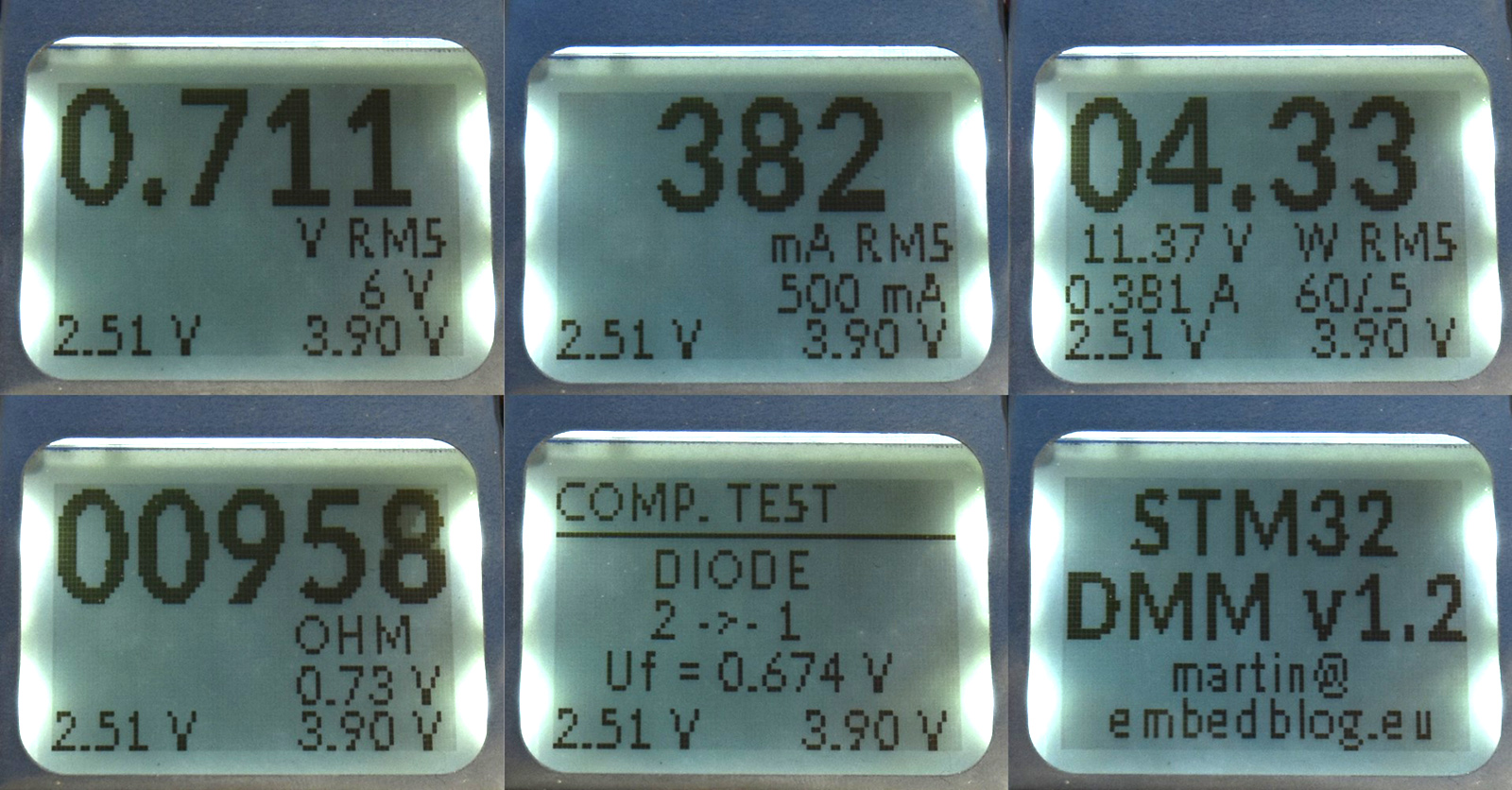
One of the most interesting early examples was Martin’s STM32-based open source multimeter. Built around STM32 microcontrollers, the project aimed to measure voltage, current, and power, with bipolar measurements and RMS capability across multiple ranges. The design included voltage ranges such as plus or minus 6 volts and plus or minus 60 volts, current ranges, continuity and resistance testing, basic component testing, and the ability to measure voltage and current at the same time to calculate power.
That last feature is a big deal. Many ordinary meters can measure voltage or current, but not both simultaneously in a way that makes power measurement convenient. When debugging small DC systems, batteries, LED drivers, microcontroller boards, or low-voltage power rails, watching voltage, current, and watts together can save a lot of probe juggling. Fewer probe gymnastics means fewer accidental shorts, fewer confused readings, and fewer moments where you mutter “that was working five seconds ago” at a defenseless circuit board.
The STM32 project also showed the maker value of approachable design. It used multiple PCBs, a compact display, USB-related features, and a 3D-printed enclosure. It was not trying to dethrone a high-end calibrated bench meter. It was trying to prove that a usable digital multimeter could be open, documented, and built with widely available components. That is exactly the sort of project that teaches more than a finished black-box product ever could.
HydraMeter: The Open Source Multimeter Grows More Heads
The newer HydraMeter project pushes the concept further. Created by John Duffy, HydraMeter is an open source, highly modular multimeter with an unusually opinionated design philosophy. The name fits: like the mythological Hydra, the project imagines test equipment as a family of connected, swappable, upgradeable heads rather than one sealed instrument doing one fixed job forever.
The project’s design goals are unusually practical. HydraMeter emphasizes a modular front end, detachable or wireless display concepts, isolated USB, graphical display capability, easy fuse replacement, long battery life, high diode-test voltage for lighting modern LEDs, and simultaneous voltage and current measurement. It also explores a very physical question that software people sometimes forget: how should a tool feel in the hand?
That last point is not fluff. A multimeter lives in a hand, on a bench, under a dashboard, next to a power supply, or balanced in a position that violates both ergonomics and common sense. If the display is unreadable, the range selection is confusing, the continuity beep is delayed, or the fuse requires a miniature archaeological dig to replace, the instrument becomes annoying no matter how clever the circuit is.
Open Source Does Not Mean “Casual About Safety”
Here is where we pause the celebration and put on the safety glasses. A multimeter is not just another microcontroller board. It connects to the outside world, and the outside world can be rude. Sometimes it is a harmless 3.3-volt signal. Sometimes it is a 12-volt battery with enough current to vaporize a careless probe tip. Sometimes it is mains power, high-energy industrial wiring, or a capacitor that has been quietly waiting to ruin your afternoon.
Good meter design must consider input protection, fuses, creepage and clearance, transient overvoltage, burden voltage, range switching, and user error. Because users will make errors. They will measure voltage while the lead is still in the current jack. They will forget the last range. They will poke a live panel while thinking about lunch. The meter must be designed for the human being actually using it, not the perfect laboratory angel imagined in a datasheet.
This is why CAT safety ratings matter. CAT II, CAT III, and CAT IV ratings are not decorative stickers for the meter’s ego. They indicate where and how a meter is intended to handle transient overvoltage conditions. A meter suitable for low-energy electronics work is not automatically safe for distribution panels, utility service entrances, or industrial environments. Open source projects can teach us a lot, but a DIY meter should not be treated as a certified replacement for a properly rated professional instrument when working on dangerous circuits.
What Makes a Digital Multimeter Good?
A digital multimeter looks simple because the screen gives you a number. Behind that number is a pile of engineering. A good DMM starts with stable analog front ends for voltage, current, and resistance. It needs accurate scaling networks, low-noise measurement paths, protection components that do not ruin accuracy, and an analog-to-digital converter good enough for the job.
The STM32F373 family is interesting for projects like this because it includes 16-bit sigma-delta ADCs, which are useful for precision measurement applications. That does not magically create a precision instrument by itself. The ADC is only one member of the band. The resistors, references, layout, shielding, calibration, firmware filtering, and thermal behavior all need to show up on time and play in tune.
Voltage Measurement
Voltage measurement usually involves scaling the input down to a level the electronics can safely read. That sounds easy until you remember that a meter may need to read millivolts one minute and dozens or hundreds of volts the next. High-value divider resistors, protection devices, switching leakage, input impedance, noise, and calibration all become part of the story. Good design is not merely “divide voltage, read ADC, profit.” If it were, multimeter engineers would have much shorter meetings.
Current Measurement
Current measurement often uses a shunt resistor. The meter measures the voltage drop across the shunt and calculates current using Ohm’s law. This introduces burden voltage, heat, fuse requirements, and range-selection challenges. A low-current range needs sensitivity; a high-current range needs durability. Asking one instrument to handle microamps and amps is like asking a house cat to also be a forklift. Possible? No. But with clever engineering, the meter can at least act civilized across a wide range.
Resistance and Continuity
Resistance mode usually sends a small known current through the unknown resistance and measures the resulting voltage. Continuity is the impatient cousin of resistance mode. Instead of displaying a precise value, it answers the urgent question: “Are these two points connected?” A fast continuity beep is one of those features that separates a beloved meter from one that gets exiled to the drawer of questionable adapters.
True RMS and Why Waveforms Refuse to Behave
True RMS measurement matters when AC waveforms are not clean sine waves. In a perfect classroom, AC is smooth, symmetrical, and well dressed. In the real world, switching power supplies, dimmers, motor drives, inverters, LED drivers, and chopped waveforms show up wearing muddy boots. Average-responding meters can be fine for simple sine-wave measurements, but true RMS meters are designed to calculate the effective value of more complicated AC waveforms.
For an open source multimeter, RMS capability is a serious design achievement because it touches both hardware and firmware. The instrument has to sample appropriately, manage offsets, scale the signal, and calculate the value correctly. It also has to be honest about bandwidth and limits. A meter can be true RMS and still not be the right tool for every waveform. Marketing departments sometimes forget that last sentence, probably because it does not fit well on a shiny sticker.
Open Hardware Turns a Meter Into a Classroom
The best part of an open source multimeter is not that everyone will build one. Many people will not. Surface-mount assembly, calibration, enclosure design, and safe input protection are not casual weekend tasks for beginners. The real value is that the design becomes visible. Students can trace measurement paths. Makers can compare analog front-end approaches. Firmware developers can study filtering and display logic. Mechanical designers can see how enclosure choices affect usability.
Open designs also invite specialization. One user might want a meter optimized for low-voltage embedded systems. Another might want better logging. Another might want a detachable display. Someone else might want a quieter enclosure, different switches, a rotary selector, bigger digits, or a continuity mode that responds faster than a sleepy elevator. Open source makes those conversations productive because people can modify actual source files rather than merely complain into the void.
The User Interface Debate: Switches, Menus, and Muscle Memory
HydraMeter’s interface is fascinating because it challenges the familiar rotary-dial model. Toggle switches and visible configuration states can make the meter’s setup obvious at a glance once you learn the layout. The tradeoff is that new users may find it less immediately familiar than a conventional dial. That is classic open hardware territory: a design choice that some people love, some people dislike, and everyone can argue about with suspicious enthusiasm.
There is no perfect multimeter interface. Rotary switches are familiar and fast, but they can hide secondary functions. Menus add power but slow down common tasks. Soft keys are flexible but can feel like programming a microwave. Toggle switches are explicit but may look busy. The open source advantage is that the interface is not sacred. If the community wants a different front panel, display layout, or control scheme, the files are there to study and change.
Calibration: The Difference Between a Number and a Measurement
A multimeter does not become trustworthy just because it displays digits. Calibration compares the meter against known references and identifies how close the readings are across ranges and functions. Voltage, current, resistance, frequency, capacitance, and other functions may each require different test points and procedures. High-end labs use traceable standards and carefully controlled conditions. Hobbyists may use voltage references, known resistors, or comparisons against better instruments, but should understand the limits of those methods.
For an open source meter, calibration is especially important because builders may use different components, assembly techniques, firmware versions, and enclosures. A design can be clever and still need calibration. In fact, the cleverer the design, the more tempting it is to believe the numbers without checking them. That is how test equipment becomes a confidence machine instead of a measurement tool.
What an Open Source Multimeter Should Include
A strong open source digital multimeter project should include more than a schematic. It should provide native design files, bill of materials, firmware source, calibration instructions, safety notes, enclosure files, assembly guidance, known limitations, and test results. It should clearly state what the meter is and is not intended to measure. It should also avoid pretending that “open” means “professionally certified.” Transparency is powerful, but it does not replace safety testing.
Ideally, the project should be designed with accessible tools such as KiCad or other widely available electronics design software. It should use components that can be purchased without hunting through suspicious online listings titled “100% original maybe.” It should document substitutions, firmware flashing, display modules, battery charging, fusing, and expected accuracy. Good documentation is the difference between open source and open mystery.
Specific Examples: Where This Could Shine
An open source multimeter is especially useful in education. Imagine a lab where students do not just learn how to use a meter, but also learn how the meter works. They could measure a resistor, then examine the ohms circuit. They could compare RMS and DC readings, then review the sampling math. They could intentionally blow a fuse in a controlled training setup and learn why current ranges deserve respect.
It could also shine in embedded development. A meter with serial logging, isolated USB, and easy data export would be excellent for watching battery drain, sleep current, regulator behavior, or sensor power profiles. Pair that with a detachable display or graphical trend view, and suddenly the meter becomes more than a number box. It becomes a small data instrument for real debugging.
Repair communities could benefit too. A documented meter can be repaired, modified, and improved. If a display fails, a switch wears out, or a firmware bug appears, the project does not have to disappear into landfill with a tiny sad beep. Repairability is not a romantic bonus; it is part of responsible tool design.
The Honest Limitations
Open source multimeters are exciting, but they are not automatically better than commercial meters. A well-made professional meter brings safety certifications, ruggedness, predictable performance, support, calibration services, and years of design refinement. Open projects bring visibility, flexibility, learning value, and community improvement. Those are different strengths.
If you are working on mains wiring, industrial panels, HVAC systems, electric vehicles, or anything with serious energy behind it, use properly rated equipment from reputable manufacturers. If you are learning electronics, building low-voltage projects, debugging microcontroller circuits, studying analog measurement, or exploring test equipment design, an open source multimeter project can be a gold mine.
Experience Notes: What It Feels Like to Want This Tool
Anyone who spends enough time building electronics eventually develops a strange relationship with multimeters. You start with one cheap meter. Then you buy a better one. Then you keep the cheap one because it is “still useful.” Then another meter appears, possibly through spontaneous generation. Before long, there is one on the bench, one in the toolbox, one in a drawer, and one that nobody trusts but nobody throws away because it still beeps in continuity mode if you hold it at the correct angle.
The appeal of an open source multimeter becomes obvious in those everyday moments. You are debugging a small power board and wish the meter logged current over time. You are checking LED polarity and the diode mode will not provide enough voltage to light a white LED. You are measuring a low-current sleep mode and wondering how much burden voltage is affecting the circuit. You are using continuity mode and the beep arrives just late enough to make you question your life choices. These annoyances are tiny, but tools are made of tiny experiences.
A hackable meter changes the emotional tone of the workbench. Instead of accepting every limitation as permanent, you start thinking in terms of design decisions. The slow continuity beep is not fate; it is firmware, filtering, hardware, or a deliberate compromise. The display layout is not a decree from Mount Measurement; it is pixels. The enclosure is not sacred; it is CAD. The data output is not locked away; it can be documented, parsed, logged, and improved.
There is also a satisfying educational loop. When a meter reads 4.98 volts on a 5-volt rail, most users simply accept the number. With an open design, you can ask why. What reference is being used? What tolerance are the divider resistors? Has the meter warmed up? Is the input impedance loading anything? Has it been calibrated? This turns a simple reading into a lesson in measurement uncertainty, and that lesson is worth more than yet another glossy gadget.
Building or studying an open source multimeter can also make you more respectful of commercial meters. Once you see the design problems up close, the price of a reliable professional DMM starts to make more sense. Protection alone is a serious engineering problem. Good fuses cost money. Safe spacing takes board area. Accurate resistors cost more than mystery resistors. Enclosures are harder than they look. Rubber holsters are not just decorative tool pajamas. A meter that survives abuse is the product of many unglamorous decisions.
That is why open source test equipment is so valuable: it does not have to replace every commercial tool to matter. It can teach, inspire, and improve the ecosystem. It can give advanced hobbyists a platform to customize. It can give educators a transparent instrument. It can push manufacturers to think harder about repairability and data access. And it can give the rest of us something wonderful to stare at while whispering, “I definitely need this,” even though three meters are already sitting within arm’s reach.
Conclusion: Finally, a Meter We Can Argue With Productively
An open source multimeter is exciting because it opens the case, literally and philosophically. Projects like the STM32 Open Source Multimeter and HydraMeter show that makers are not satisfied with sealed tools when those tools could also be platforms. They want measurement, logging, modularity, repairability, better interfaces, and the freedom to learn from the design.
The result is not just a gadget. It is an invitation. It asks electronics enthusiasts to think more deeply about voltage, current, resistance, RMS, calibration, protection, and user experience. It reminds us that even the most familiar bench tool can be reimagined. And it proves that “open source multimeter” is no longer just a wish floating around maker forums. It is real, evolving, and wonderfully nerdy in the best possible way.