Note: This article discusses low-voltage electronic-device troubleshooting. Disconnect power before opening gear, use proper ESD precautions, and leave mains-powered repairs to qualified technicians.
A MIDI sequencer with a dead display is the electronic-music equivalent of a car with a perfectly healthy engine and no dashboard. It may still be capable of doing important things, but good luck knowing whether it is recording, playing, muting a track, or quietly judging your last bass line.
That was the challenge behind Leo’s repair of a Social Entropy Engine MIDI sequencer. The unit belonged to a musician, and its display had stopped working. The manufacturer suspected a display-driver integrated circuit and supplied a replacement chip. That sounds wonderfully straightforward until you remember that electronic repairs are rarely polite enough to introduce themselves with a name tag.
The repair became a useful lesson in practical MIDI sequencer troubleshooting: start with the symptom, question the obvious answer, protect nearby components, inspect every solder joint, and only then bring out the hot-air rework station. In other words, do not replace an IC just because it is standing suspiciously close to the crime scene.
Why a MIDI Sequencer Display Failure Matters
A hardware MIDI sequencer does much more than flash lights and make a room look like it belongs in a 1980s sci-fi movie. It stores patterns, sends note data, handles timing, controls MIDI channels, recalls song arrangements, and often manages transport commands such as play, stop, and continue.
The Social Entropy Engine is a multitrack pattern sequencer designed to control hardware and software instruments. Its screen and front-panel controls are central to using functions such as step editing, pattern selection, track settings, timing adjustments, and MIDI routing. When the display goes dark, the sequencer may still have a functioning processor and MIDI output, but the musician loses the map needed to operate it confidently.
This is why a dead display does not automatically mean a dead sequencer. The fault could be limited to the display itself, the display-driver IC, a connector, a damaged trace, a power rail, a cracked solder joint, or the logic signal that tells the display what to show. The display is a symptom location, not necessarily the whole diagnosis.
The First Suspect: A Bad Solder Joint
Leo’s first instinct was sensible. Because users repeatedly press front-panel switches mounted to the circuit board, mechanical stress can eventually affect nearby solder joints. A tiny crack can interrupt a connection even though the joint still looks almost normal from above. Electronics have a special talent for hiding their problems in places that require a magnifier, a good lamp, and at least one muttered complaint.
Before replacing a surface-mount chip, it makes sense to inspect the board for:
- Cracked or dull solder joints around switches, connectors, and display pins.
- Lifted pads, damaged copper traces, or board flex near high-use controls.
- Oxidation, liquid residue, corrosion, or old flux that obscures a joint.
- Loose cables between the main board, display board, and control panel.
- Burned components, swollen capacitors, or unusual heat marks.
In Leo’s case, the bad-joint theory did not solve the problem. That was not wasted time. It ruled out one of the most common and least expensive explanations before a more invasive repair began.
Reflowing the Display Driver Without Roasting the Neighborhood
The next move was to reflow the suspected display-driver chip with hot air. Reflowing means heating existing solder enough to allow it to settle and reconnect properly. It can help when a solder joint has become unreliable, but it is not a magic spell. If the integrated circuit itself has failed internally, the board can look beautifully reflowed and remain every bit as unhelpful as before.
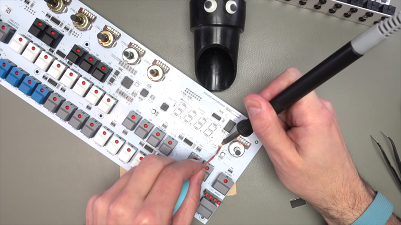
The nearby seven-segment LEDs created an extra challenge. These displays are not fans of uncontrolled heat, especially when they are sitting close to a hot-air nozzle that behaves like a tiny weather event. Leo used a foil shield to protect the LEDs while working on the driver IC. That small precaution reflects a larger repair principle: heat only the area that truly needs heat.
For a MIDI sequencer repair involving surface-mount parts, careful technicians typically use magnification, controlled airflow, suitable flux, and a stable board holder. They avoid chasing a component around the board with a soldering iron like it owes them money. A repair should be deliberate, not theatrical.
Why Reflow Did Not End the Story
When reflowing the existing chip did not restore the display, the evidence pointed more strongly toward the driver IC itself or a fault directly associated with it. The replacement chip supplied by the manufacturer now made more sense as the next step.
This is a good example of diagnosis by elimination. Leo did not begin by assuming the manufacturer was wrong. He simply tested a lower-risk possibility first. That approach protects the board, saves replacement parts, and builds confidence that the final repair addresses the actual cause rather than a convenient guess.
Removing and Replacing a Surface-Mount Driver IC
Once the original driver IC was identified as the likely failed part, Leo used hot air to remove it. Afterward, the pads were cleaned with a soldering iron and solder wick. This stage matters because old solder, excess flux, solder bridges, or uneven pads can turn a good replacement part into a brand-new problem.
Surface-mount soldering is less about brute force than control. The goal is to create clean electrical connections without lifting pads, overheating adjacent parts, or joining pins that were never meant to meet. A small amount of fresh solder, careful alignment, and close inspection are much more valuable than a heroic amount of heat.
Leo installed the replacement IC using a fine soldering approach. Once the chip was in place, the repair could finally be tested. The display returned, and the sequencer was back in business. Somewhere, a pattern sequence was likely preparing to repeat for sixteen glorious steps.
What Makes a MIDI Sequencer Different From Ordinary Electronics
A MIDI sequencer repair is not only about getting lights to turn on. The device must also communicate accurately with other gear. MIDI messages commonly travel through a serial connection, while traditional five-pin DIN MIDI ports use a defined electrical interface designed for reliable communication between instruments.
A working display is excellent news, but the repair is incomplete until the sequencer can perform its musical job. After any display or logic-board repair, test more than the visible symptom. A proper validation routine should include:
- Power-up behavior and display readability.
- Buttons, encoders, switches, and transport controls.
- Pattern loading, editing, saving, and recall.
- MIDI input and MIDI output using known-good cables.
- Correct MIDI channel assignment for connected instruments.
- MIDI clock, start, stop, and continue behavior.
- Playback timing at different tempos and pattern lengths.
MIDI Clock is particularly important in a hardware setup. It sends timing pulses that allow compatible devices to stay synchronized. A sequencer can appear healthy while still producing confusing results if a clock loop, wrong sync source, channel mismatch, or transport setting is hiding elsewhere in the rig.
A Better Troubleshooting Order for MIDI Sequencer Repair
The most useful takeaway from Leo’s repair is not simply “replace the display chip.” It is the order of operations. A thoughtful sequence prevents expensive mistakes and gives each test a purpose.
1. Confirm the Exact Failure
Is the display completely blank, partially lit, dim, flickering, frozen, or showing corrupted characters? Does the sequencer still send MIDI notes? Do buttons respond? Does the issue appear every time or only after the unit warms up? Write down the symptom before touching anything.
2. Rule Out External Causes
Use the correct power supply, inspect cables, and test with a known-good MIDI cable and receiving instrument. A damaged adapter or loose connector can imitate a complex internal problem with impressive confidence.
3. Check Power Before Replacing Logic
Digital circuits depend on stable supply rails. A voltage rail that is too low, unstable, or noisy can cause blank displays, random resets, unreliable buttons, and corrupted behavior. A multimeter can confirm basic voltage presence, while an oscilloscope is more useful for checking ripple or intermittent noise.
4. Inspect Mechanical Stress Points
Switches, encoders, power jacks, MIDI ports, and display connectors are frequent trouble spots because people interact with them physically. Inspect these areas under magnification before attacking fine-pitch ICs.
5. Reflow Only When Evidence Supports It
Reflowing can repair a poor joint, but it should not be used as a universal first response. Heat can damage plastic parts, weaken pads, disturb nearby components, and hide the real fault for a short time. Use it when inspection, testing, or known failure patterns make it reasonable.
6. Replace the Suspect Part Carefully
When a replacement IC is available and the evidence supports it, remove the faulty device with proper tools. Clean the pads, align the replacement precisely, inspect for bridges, and test before fully reassembling the enclosure.
Common MIDI Sequencer Repair Mistakes to Avoid
Replacing parts at random. This gets expensive quickly and can introduce additional faults. Diagnose first, replace second.
Assuming the display is the processor. A blank screen can make a sequencer feel dead even when its CPU and MIDI engine are still operating.
Using too much heat. Hot air is useful, but it can melt connectors, shift tiny components, or damage LEDs when used carelessly.
Skipping ESD protection. Sensitive chips can be harmed by electrostatic discharge. Work on a clean surface, avoid synthetic-clothing chaos, and use proper ESD handling practices.
Testing only one function afterward. Seeing a repaired display is satisfying, but a sequencer should also record, play, save, sync, and send MIDI correctly.
Ignoring documentation. Service notes, pinouts, schematics, user manuals, and manufacturer support can turn hours of guessing into a focused repair. Even the most confident technician should accept help from a diagram.
Hands-On Repair Experiences: Lessons From the Bench
Anyone who has spent time around synthesizers, drum machines, MIDI interfaces, or hardware sequencers eventually learns that electronic faults have personalities. Some are dramatic. A device will not power on, the screen is black, and the problem announces itself like a thunderstorm. Others are sneaky. A button works only when pressed at a particular angle. A display flickers after twenty minutes. MIDI timing drifts only when three devices are connected and one of them has decided that it, too, should be the master clock.
One common experience is discovering that the symptom is much smaller than the fear it creates. A blank display can make a musician assume that an entire sequencer is finished. Yet after basic testing, the unit may still send notes, respond to transport commands, or play stored patterns. That changes the repair strategy immediately. Instead of treating the device as a total failure, the technician can focus on the display path: power, connector, driver, LEDs, logic lines, and solder joints.
Another familiar experience is finding a fault near a control that gets used constantly. Transport buttons, tempo encoders, MIDI sockets, and power jacks live hard lives. People press them during rehearsals, shove cables into them during setup, and occasionally transport the gear in bags that offer roughly the protection of a tortilla. Repeated movement can stress a joint or connector long before a semiconductor fails.
There is also a valuable emotional lesson in working slowly. The urge to replace the most suspicious chip immediately is strong, especially when a replacement part is sitting on the bench making eye contact. But good repair work often begins with observation. A close inspection may reveal a lifted pad. A continuity check may expose a broken trace. A known-good power supply may solve what looked like a complex display failure. Every simple test that rules something out narrows the path forward.
Surface-mount rework teaches humility fast. Tiny IC pins can look perfectly aligned until magnification reveals one bent leg or a microscopic solder bridge. Flux becomes less of a messy nuisance and more of a quiet assistant. Solder wick, used patiently, can clean pads beautifully. Used carelessly, it can lift a pad and turn a thirty-minute job into an archaeology project.
Testing after repair provides the best kind of payoff. First, the display wakes up. Then buttons respond. Then the sequencer talks to a synth, starts a pattern, sends clock data, and locks a small collection of machines into one shared groove. It is hard not to smile at that moment. A repaired MIDI sequencer is not merely a circuit board with restored voltage; it is a creative tool returning to the musician who depends on it.
The larger experience is this: repair work rewards patience. The best results rarely come from the fastest person with the hottest tool. They come from someone who observes carefully, measures methodically, respects heat and static, and verifies every function before declaring victory. That is how a little sequencer gets another chance to make a lot of noise.
Conclusion: A Small Repair With a Big Musical Result
Leo’s MIDI sequencer repair shows why methodical diagnosis beats guesswork. The dead display initially suggested a failed driver IC, but the repair process still began with a practical check for damaged solder joints around heavily used switches. After reflowing did not solve the problem, careful hot-air removal, pad cleanup, and replacement of the display-driver chip restored the sequencer.
The lesson applies to nearly any MIDI sequencer, groovebox, drum machine, or synth with a display problem. Start with the simplest evidence, verify stable power, inspect stress points, protect nearby components during rework, and test every musical function after repair. When done well, MIDI sequencer repair is not just electronics maintenance. It is a way of keeping useful, expressive instruments alive long after their warranties have gone to live on a farm.